


V
- 32
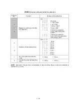
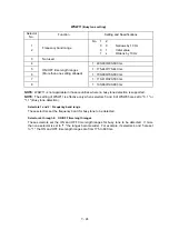
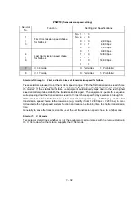
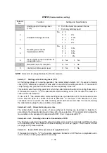
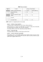
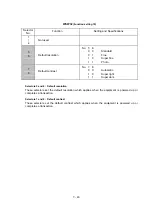
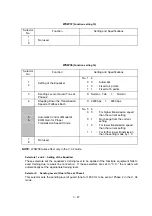
WSW19
(Transmission speed setting)
Selector
No.
Function
Setting and Specifications
1
|
3
First transmission speed choice
for fallback
No. 1
2
3
No. 4
5
6
0
0
0
:
2,400 bps
0
0
1
:
4,800 bps
0
1
0
:
7,200 bps
4
|
6
Last transmission speed choice
for fallback
0
1
1
:
9,600 bps
1
0
0
:
12,000 bps
1
0
1
:
1
1
0
:
14,400 bps
1
1
1
:
7
V. 34 mode
0:
Permitted
1:
Prohibited
8
V. 17 mode
0:
Permitted
1:
Prohibited
l
Selectors 1 through 6: First and last choices of transmission speed for fallback
These selectors are used to set the modem speed range. With the first transmission speed choice
specified by selectors 1 through 3, the equipment attempts to establish the transmission link via
the modem. If the establishment fails, the equipment automatically steps down to the next highest
speed and attempts to establish the transmission link again. The equipment repeats this sequence
while stepping down the transmission speed to the last choice specified by selectors 4 through 6.
If the modem always falls back to a low transmission speed (e.g., 4,800 bps), set the first
transmission speed choice to the lower one (e.g., modify it from 12,000 bps to 7,200 bps) in order
to deactivate the high-speed modem function and reduce the training time for shorter transmission
time.
Generally, to save the transmission time, set the last transmission speed choice to a higher one.
l
Selector 7:
V. 34 mode
This selector determines whether or not the equipment communicates with the remote station in
the V. 34 mode when that station supports the V. 34 mode.
Содержание FAX-8650P
Страница 1: ...FACSIMILE EQUIPMENT SERVICE MANUAL MODEL FAX3750 FAX 8650P MFC7750 ...
Страница 5: ...CHAPTER I GENERAL DESCRIPTION ...
Страница 12: ...CHAPTER II INSTALLATION ...
Страница 13: ...CONTENTS 1 INSTALLING THE UPDATE DATA TO THE FACSIMILE EQUIPMENT II 1 ...
Страница 16: ...CHAPTER III THEORY OF OPERATION ...
Страница 18: ...III 1 1 OVERVIEW Not provided on the FAX 8650P ...
Страница 21: ...III 4 2 2 Laser Printing Mechanism 2 2 1 Paper pulling in registration feeding and ejecting mechanism ...
Страница 28: ...III 11 Not provided on the FAX 8650P Location of Sensors and Actuators ...
Страница 31: ...III 14 Main PCB Modem PCB ...
Страница 36: ...CHAPTER IV DISASSEMBLY REASSEMBLY AND LUBRICATION ...
Страница 42: ...IV 4 n n Disassembly Order Flow ...
Страница 71: ...IV 33 1 Provided on the FAX 8650P 2 Not provided on the FAX 8650P ...
Страница 72: ...IV 34 Setting up the main PCB after replacement ...
Страница 84: ...IV 46 2 Control panel locks 3 Scanner frame ASSY and separation roller gear ...
Страница 85: ...IV 47 4 Top cover lock spring 5 Gear drive unit ...
Страница 86: ...CHAPTER V MAINTENANCE MODE ...
Страница 93: ...V 6 Scanning Compensation Data List ...
Страница 141: ...V 54 FAX3750 FAX 8650P MFC7750 Key Button Entry Order ...
Страница 146: ...CHAPTER VI ERROR INDICATION AND TROUBLESHOOTING ...
Страница 171: ...Oct 98 SM5X5303 Printed in Japan ...
Страница 172: ...FAX3750 FAX 8650P MFC7750 Appendix 1 EEPROM Customizing Codes ...
Страница 194: ......
Страница 195: ......
Страница 196: ......


