


IV
- 3
n
n
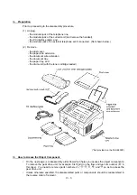
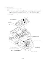
Preparation
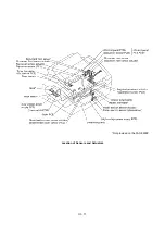
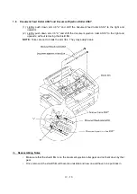
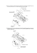
Prior to proceeding to the disassembly procedure,
(1) Unplug
- the modular jack of the telephone line,
- the modular jack of the curled cord (and remove the handset),
- the PC interface cable, and
- the modular jack of an external telephone set if connected. (Not shown below.)
(2) Remove
- the dust cover,
- the paper wire extension
- the document wire extension
- the document tray,
- the paper tray, and
- the drum unit (with the toner cartridge loaded)
(*Not provided on the FAX-8650P)
n
n
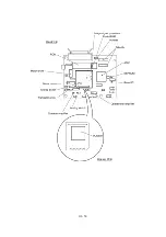
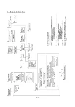
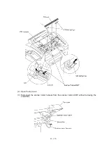
How to Access the Object Component
•
On the next page is a disassembly order flow which helps you access the object components.
To remove the gear drive unit, for example, first find it on the flow and learn its number (
in
this case). You need to remove parts numbered , , ,
,
, and
so as to access the
gear drive unit.
•
Unless otherwise specified, the disassembled parts or components should be reassembled in
the reverse order of removal.
Содержание FAX-8650P
Страница 1: ...FACSIMILE EQUIPMENT SERVICE MANUAL MODEL FAX3750 FAX 8650P MFC7750 ...
Страница 5: ...CHAPTER I GENERAL DESCRIPTION ...
Страница 12: ...CHAPTER II INSTALLATION ...
Страница 13: ...CONTENTS 1 INSTALLING THE UPDATE DATA TO THE FACSIMILE EQUIPMENT II 1 ...
Страница 16: ...CHAPTER III THEORY OF OPERATION ...
Страница 18: ...III 1 1 OVERVIEW Not provided on the FAX 8650P ...
Страница 21: ...III 4 2 2 Laser Printing Mechanism 2 2 1 Paper pulling in registration feeding and ejecting mechanism ...
Страница 28: ...III 11 Not provided on the FAX 8650P Location of Sensors and Actuators ...
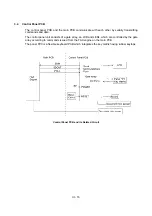
Страница 31: ...III 14 Main PCB Modem PCB ...
Страница 36: ...CHAPTER IV DISASSEMBLY REASSEMBLY AND LUBRICATION ...
Страница 42: ...IV 4 n n Disassembly Order Flow ...
Страница 71: ...IV 33 1 Provided on the FAX 8650P 2 Not provided on the FAX 8650P ...
Страница 72: ...IV 34 Setting up the main PCB after replacement ...
Страница 84: ...IV 46 2 Control panel locks 3 Scanner frame ASSY and separation roller gear ...
Страница 85: ...IV 47 4 Top cover lock spring 5 Gear drive unit ...
Страница 86: ...CHAPTER V MAINTENANCE MODE ...
Страница 93: ...V 6 Scanning Compensation Data List ...
Страница 141: ...V 54 FAX3750 FAX 8650P MFC7750 Key Button Entry Order ...
Страница 146: ...CHAPTER VI ERROR INDICATION AND TROUBLESHOOTING ...
Страница 171: ...Oct 98 SM5X5303 Printed in Japan ...
Страница 172: ...FAX3750 FAX 8650P MFC7750 Appendix 1 EEPROM Customizing Codes ...
Страница 194: ......
Страница 195: ......
Страница 196: ......


