


IV
- 28
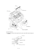
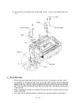
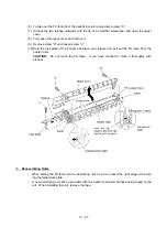
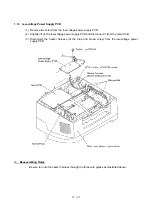
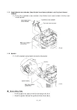
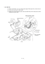
1.11 Laser Unit and Toner Sensor PCB
(1) Remove the screw (Taptite, cup B M3x8) from the toner sensor PCB.
(2) Slightly lift up the toner sensor PCB and disconnect its harness.
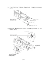
(3) Remove the three screws from the laser unit.
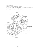
(4) Slightly lift up the laser unit and disconnect the following from the main PCB:
- Laser diode harness (5-pin)
- Toner sensor harness (4-pin) if the toner sensor PCB is installed
- Polygon motor flat cable
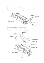
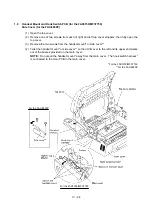
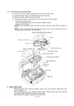
NOTE:
When handling the laser unit, take care not to touch the inside of the unit, glass, or
mirror.
NOTE:
On the small PCB at the right side of the laser unit is a 2-pin connector which is for
the adjustment in the factory. Do not disturb it.
n
n
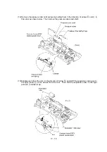
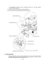
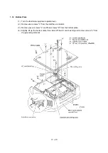
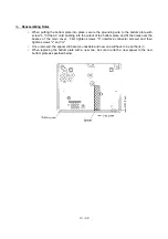
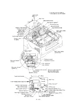
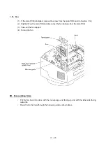
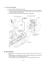
Reassembling Notes
•
Before putting the laser unit back into place, check for any toner particles, paper dust or dirt,
and clean them out.
•
When installing the laser unit, make sure that the laser diode harness, toner sensor harness
and polygon motor flat cable are routed as shown above.
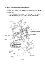
•
Make sure that the sponge is placed below the laser unit.
Содержание FAX-8650P
Страница 1: ...FACSIMILE EQUIPMENT SERVICE MANUAL MODEL FAX3750 FAX 8650P MFC7750 ...
Страница 5: ...CHAPTER I GENERAL DESCRIPTION ...
Страница 12: ...CHAPTER II INSTALLATION ...
Страница 13: ...CONTENTS 1 INSTALLING THE UPDATE DATA TO THE FACSIMILE EQUIPMENT II 1 ...
Страница 16: ...CHAPTER III THEORY OF OPERATION ...
Страница 18: ...III 1 1 OVERVIEW Not provided on the FAX 8650P ...
Страница 21: ...III 4 2 2 Laser Printing Mechanism 2 2 1 Paper pulling in registration feeding and ejecting mechanism ...
Страница 28: ...III 11 Not provided on the FAX 8650P Location of Sensors and Actuators ...
Страница 31: ...III 14 Main PCB Modem PCB ...
Страница 36: ...CHAPTER IV DISASSEMBLY REASSEMBLY AND LUBRICATION ...
Страница 42: ...IV 4 n n Disassembly Order Flow ...
Страница 71: ...IV 33 1 Provided on the FAX 8650P 2 Not provided on the FAX 8650P ...
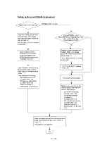
Страница 72: ...IV 34 Setting up the main PCB after replacement ...
Страница 84: ...IV 46 2 Control panel locks 3 Scanner frame ASSY and separation roller gear ...
Страница 85: ...IV 47 4 Top cover lock spring 5 Gear drive unit ...
Страница 86: ...CHAPTER V MAINTENANCE MODE ...
Страница 93: ...V 6 Scanning Compensation Data List ...
Страница 141: ...V 54 FAX3750 FAX 8650P MFC7750 Key Button Entry Order ...
Страница 146: ...CHAPTER VI ERROR INDICATION AND TROUBLESHOOTING ...
Страница 171: ...Oct 98 SM5X5303 Printed in Japan ...
Страница 172: ...FAX3750 FAX 8650P MFC7750 Appendix 1 EEPROM Customizing Codes ...
Страница 194: ......
Страница 195: ......
Страница 196: ......


