


V
- 42
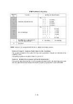
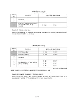
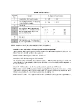
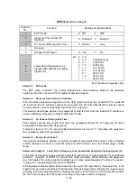
WSW31
(Function setting 9)
Selector
No.
Function
Setting and Specifications
1
Not used.
2
Default reduction rate for failure of
automatic reduction during
recording
0:
100%
1:
75% (Letter)
87% (A4)
95% (Legal)
3
4
Not used.
5
Minimum short-OFF duration in
distinctive ringing
0:
130 ms
1:
90 ms
6
|
8
Not used.
l
Selector 2:
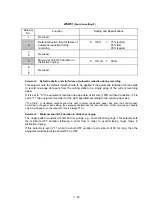
Default reduction rate for failure of automatic reduction during recording
This selector sets the default reduction rate to be applied if the automatic reduction function fails
to record one-page data sent from the calling station in a single page of the current recording
paper.
If it is set to "0," the equipment records one-page data at full size (100%) without reduction; if it is
set to "1," the equipment records it at the size* specified according to the current paper size.
(*The U.S.A. or Canadian versions allow the user to select the desired paper size from the control panel.
According to the paper size setting, the equipment determines the reduction rate. Other versions can handle
only A4-size paper, so the reduction rate is always 87%.)
l
Selector 5:
Minimum short-OFF duration in distinctive ringing
The ringer pattern consists of short and long rings, e.g., short-short-long rings. This selector sets
the minimum OFF duration following a short ring in order to avoid missing ringer tones in
distinctive ringing.
If this selector is set to "1," when the short-OFF duration is a minimum of 90 ms long, then the
equipment will interpret the short-OFF as OFF.
Содержание FAX-8650P
Страница 1: ...FACSIMILE EQUIPMENT SERVICE MANUAL MODEL FAX3750 FAX 8650P MFC7750 ...
Страница 5: ...CHAPTER I GENERAL DESCRIPTION ...
Страница 12: ...CHAPTER II INSTALLATION ...
Страница 13: ...CONTENTS 1 INSTALLING THE UPDATE DATA TO THE FACSIMILE EQUIPMENT II 1 ...
Страница 16: ...CHAPTER III THEORY OF OPERATION ...
Страница 18: ...III 1 1 OVERVIEW Not provided on the FAX 8650P ...
Страница 21: ...III 4 2 2 Laser Printing Mechanism 2 2 1 Paper pulling in registration feeding and ejecting mechanism ...
Страница 28: ...III 11 Not provided on the FAX 8650P Location of Sensors and Actuators ...
Страница 31: ...III 14 Main PCB Modem PCB ...
Страница 36: ...CHAPTER IV DISASSEMBLY REASSEMBLY AND LUBRICATION ...
Страница 42: ...IV 4 n n Disassembly Order Flow ...
Страница 71: ...IV 33 1 Provided on the FAX 8650P 2 Not provided on the FAX 8650P ...
Страница 72: ...IV 34 Setting up the main PCB after replacement ...
Страница 84: ...IV 46 2 Control panel locks 3 Scanner frame ASSY and separation roller gear ...
Страница 85: ...IV 47 4 Top cover lock spring 5 Gear drive unit ...
Страница 86: ...CHAPTER V MAINTENANCE MODE ...
Страница 93: ...V 6 Scanning Compensation Data List ...
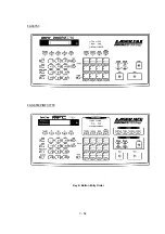
Страница 141: ...V 54 FAX3750 FAX 8650P MFC7750 Key Button Entry Order ...
Страница 146: ...CHAPTER VI ERROR INDICATION AND TROUBLESHOOTING ...
Страница 171: ...Oct 98 SM5X5303 Printed in Japan ...
Страница 172: ...FAX3750 FAX 8650P MFC7750 Appendix 1 EEPROM Customizing Codes ...
Страница 194: ......
Страница 195: ......
Страница 196: ......


