


V
- 36
l
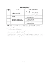
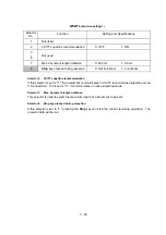
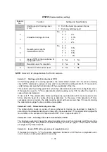
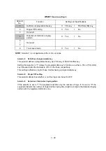
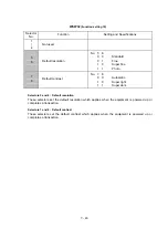
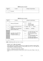
Selector 7:
Resolution level for reception
This selector determines whether the resolution should be limited at the start of reception in the
sleep mode.
l
Selector 8:
Limitation of attenuation level
Setting this selector to "0" limits the transmitting level of the modem to 10 dB.
This setting has priority over the settings selected by WSW02 (selectors 5 through 8) and WSW13
(selectors 5 through 8).
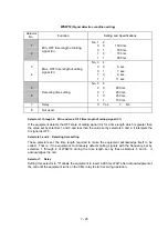
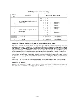
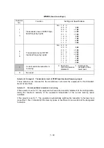
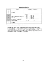
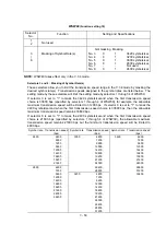
WSW24
(TAD setting 2)
Selector
No.
Function
Setting and Specifications
1
2
Not used.
3
4
Time length from CML ON to
start of pseudo ring backtone
transmission
No.
3
4
0
0
:
4 sec.
0
1
:
3 sec.
1
0
:
2 sec.
1
1
:
1 sec.
5
|
8
Attenuator for playback of ICM/
OGM to the line
(Selectable from the range of 0-
15 dB)
0:
0 dB
1:
8 dB
0:
0 dB
1:
4 dB
0:
0 dB
1:
2 dB
0:
0 dB
1:
1 dB
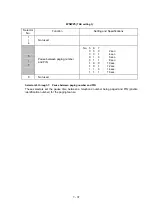
l
Selectors 3 and 4: Time length from CML ON to start of pseudo ring backtone transmission
These selectors set the length of time from CML-ON up to the start of pseudo ring backtone
transmission.
In those versions which have an OGM facility, the settings made by these selectors also apply to
the length of time from CML-ON up to the start of OGM transmission.
l
Selectors 5 through 8: Attenuator for playback of ICM/OGM to the line
Setting two or more selectors to "1" produces addition of attenuation assigned to each selector.
This setting will not be limited by selector 8 of WSW23.
Содержание FAX-8650P
Страница 1: ...FACSIMILE EQUIPMENT SERVICE MANUAL MODEL FAX3750 FAX 8650P MFC7750 ...
Страница 5: ...CHAPTER I GENERAL DESCRIPTION ...
Страница 12: ...CHAPTER II INSTALLATION ...
Страница 13: ...CONTENTS 1 INSTALLING THE UPDATE DATA TO THE FACSIMILE EQUIPMENT II 1 ...
Страница 16: ...CHAPTER III THEORY OF OPERATION ...
Страница 18: ...III 1 1 OVERVIEW Not provided on the FAX 8650P ...
Страница 21: ...III 4 2 2 Laser Printing Mechanism 2 2 1 Paper pulling in registration feeding and ejecting mechanism ...
Страница 28: ...III 11 Not provided on the FAX 8650P Location of Sensors and Actuators ...
Страница 31: ...III 14 Main PCB Modem PCB ...
Страница 36: ...CHAPTER IV DISASSEMBLY REASSEMBLY AND LUBRICATION ...
Страница 42: ...IV 4 n n Disassembly Order Flow ...
Страница 71: ...IV 33 1 Provided on the FAX 8650P 2 Not provided on the FAX 8650P ...
Страница 72: ...IV 34 Setting up the main PCB after replacement ...
Страница 84: ...IV 46 2 Control panel locks 3 Scanner frame ASSY and separation roller gear ...
Страница 85: ...IV 47 4 Top cover lock spring 5 Gear drive unit ...
Страница 86: ...CHAPTER V MAINTENANCE MODE ...
Страница 93: ...V 6 Scanning Compensation Data List ...
Страница 141: ...V 54 FAX3750 FAX 8650P MFC7750 Key Button Entry Order ...
Страница 146: ...CHAPTER VI ERROR INDICATION AND TROUBLESHOOTING ...
Страница 171: ...Oct 98 SM5X5303 Printed in Japan ...
Страница 172: ...FAX3750 FAX 8650P MFC7750 Appendix 1 EEPROM Customizing Codes ...
Страница 194: ......
Страница 195: ......
Страница 196: ......


