V
- 25
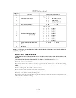
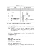
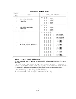
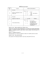
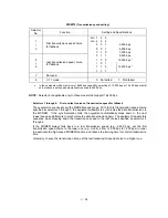
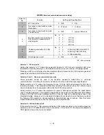
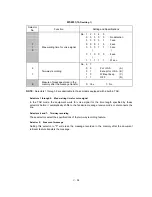
WSW12
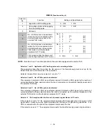
(Signal detection condition setting)
Selector
No.
Function
Setting and Specifications
1
2
Min. OFF time length of calling
signal (Ci)
No. 1
2
0
0
:
1500 ms
0
1
:
500 ms
1
0
:
700 ms
1
1
:
900 ms
3
4
Max. OFF time length of calling
signal (Ci)
No. 3
4
0
0
:
6 sec.
0
1
:
7 sec.
1
0
:
9 sec.
1
1
:
11 sec.
5
6
Detecting time setting
No. 5
6
0
0
:
800 ms (1000 ms
*
)
0
1
:
200 ms
1
0
:
250 ms
1
1
:
150 ms
7
Delay
0:
Yes
1:
No
8
Not used.
* 1000 ms in Chinese versions.
l
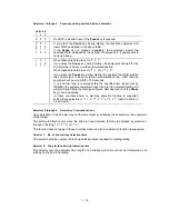
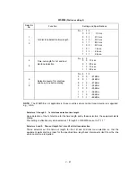
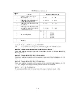
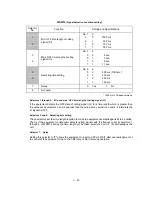
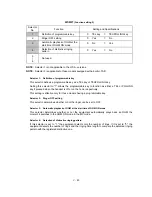
Selectors 1 through 4:
Min. and max. OFF time length of calling signal (Ci)
If the equipment detects the OFF state of calling signal (Ci) for a time length which is greater than
the value set by selectors 1 and 2 and less than the value set by selectors 3 and 4, it interprets the
Ci signal as OFF.
l
Selectors 5 and 6: Detecting time setting
These selectors set the time length required to make the equipment acknowledge itself to be called.
That is, if the equipment continuously detects calling signals with the frequency set by selectors 1
through 4 of WSW14 during the time length set by these selectors 5 and 6, it acknowledges the
call.
l
Selector 7:
Delay
Setting this selector to "0" allows the equipment to insert a 900 ms WAIT after acknowledgment of
the call until the equipment turns on the CML relay to start receiving operation.
Содержание FAX 750
Страница 4: ...CHAPTER I GENERAL DESCRIPTION ...
Страница 11: ...CHAPTER II INSTALLATION ...
Страница 12: ...CHAPTER III THEORY OF OPERATION ...
Страница 14: ...III 1 1 OVERVIEW Not provided on the FAX 910 ...
Страница 24: ...III 11 Active Gears on the Inner Side of the Drive Unit ...
Страница 26: ...III 13 Active Gears on the Inner Side of the Drive Unit ...
Страница 30: ...III 17 Location of Sensors and Actuators 1 ...
Страница 31: ...III 18 Not provided on the FAX 910 Location of Sensors and Actuators 2 ...
Страница 34: ...III 21 FAX750 FAX770 FAX 910 FAX 920 FAX 921 MFC 925 FAX870MC FAX 930 FAX 931 MFC970MC ...
Страница 39: ...CHAPTER IV DISASSEMBLY REASSEMBLY LUBRICATION AND ADJUSTMENT ...
Страница 44: ...IV 4 n n Disassembly Order Flow ...
Страница 48: ...IV 8 4 Disconnect the panel main harness ...
Страница 52: ...IV 12 ...
Страница 70: ...IV 30 Remove the two screws and lift up the paper feed chute ...
Страница 72: ...IV 32 ...
Страница 78: ...IV 38 ...
Страница 86: ...IV 46 1 17 Harness Routing ...
Страница 88: ...IV 48 ...
Страница 89: ...IV 49 2 LF roller ASSY 3 Platen frame ASSY ...
Страница 90: ...IV 50 ...
Страница 91: ...IV 51 4 Separation roller and main frame ...
Страница 92: ...CHAPTER V MAINTENANCE MODE ...
Страница 99: ...V 6 Scanning Compensation Data List ...
Страница 144: ...V 51 FAX750 FAX770 FAX 910 FAX 920 FAX 921 MFC 925 FAX870MC FAX 930 FAX 931 MFC970MC Key Button Entry Order ...
Страница 150: ...CHAPTER VI ERROR INDICATION AND TROUBLESHOOTING ...
Страница 168: ...July 98 5X4401 Printed in Japan ...
Страница 177: ......
Страница 178: ......
Страница 182: ......
Страница 184: ......
Страница 197: ......
Страница 198: ......
Страница 202: ......
Страница 216: ......
Страница 218: ......

