V
- 4
3. DETAILED DESCRIPTION OF
MAINTENANCE-MODE FUNCTIONS
3.1
EEPROM Parameter Initialization
n
n
Function
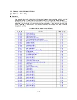
The equipment initializes the parameters, user switches, and firmware switches registered in the
EEPROM, to the initial values. Entering the function code 01 initializes all of the EEPROM areas,
but entering 91 does not initialize some areas, as listed below.
Function code
Data item
01
91
Maintenance-mode functions
User switches
Firmware switches
Remote activation code
Activity report
Distinctive ringing patterns
registered
These will be
initialized
Station ID data
Outside line number
Cover page custom comments
Remote access code
FAX forwarding/paging
Personal mailbox password
Telephone function registration
One-touch dialing
Speed dialing
Group dialing
All of these will be
initialized
These will not be
initialized
EEPROM customizing code
(4-digit)
This will not be initialized.
(Note that the first digit of the 4-digit code will be
initialized to "0." If the code is 1001, for example, it will
be initialized to 0001.)
NOTE:
If you replace the main PCB with one used for other facsimile equipment, carry out this
procedure and then customize the EEPROM (maintenance-mode function code 74 in Section 3.11).
n
n
Operating Procedure
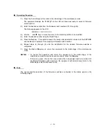
(1) Press the
0
and
1
keys (or the
9
and
1
keys according to your need) in this order in the initial
stage of the maintenance mode.
The "PARAMETER INIT" will appear on the LCD.
(2) Upon completion of parameter initialization, the equipment returns to the initial stage of the
maintenance mode.
Содержание FAX 750
Страница 4: ...CHAPTER I GENERAL DESCRIPTION ...
Страница 11: ...CHAPTER II INSTALLATION ...
Страница 12: ...CHAPTER III THEORY OF OPERATION ...
Страница 14: ...III 1 1 OVERVIEW Not provided on the FAX 910 ...
Страница 24: ...III 11 Active Gears on the Inner Side of the Drive Unit ...
Страница 26: ...III 13 Active Gears on the Inner Side of the Drive Unit ...
Страница 30: ...III 17 Location of Sensors and Actuators 1 ...
Страница 31: ...III 18 Not provided on the FAX 910 Location of Sensors and Actuators 2 ...
Страница 34: ...III 21 FAX750 FAX770 FAX 910 FAX 920 FAX 921 MFC 925 FAX870MC FAX 930 FAX 931 MFC970MC ...
Страница 39: ...CHAPTER IV DISASSEMBLY REASSEMBLY LUBRICATION AND ADJUSTMENT ...
Страница 44: ...IV 4 n n Disassembly Order Flow ...
Страница 48: ...IV 8 4 Disconnect the panel main harness ...
Страница 52: ...IV 12 ...
Страница 70: ...IV 30 Remove the two screws and lift up the paper feed chute ...
Страница 72: ...IV 32 ...
Страница 78: ...IV 38 ...
Страница 86: ...IV 46 1 17 Harness Routing ...
Страница 88: ...IV 48 ...
Страница 89: ...IV 49 2 LF roller ASSY 3 Platen frame ASSY ...
Страница 90: ...IV 50 ...
Страница 91: ...IV 51 4 Separation roller and main frame ...
Страница 92: ...CHAPTER V MAINTENANCE MODE ...
Страница 99: ...V 6 Scanning Compensation Data List ...
Страница 144: ...V 51 FAX750 FAX770 FAX 910 FAX 920 FAX 921 MFC 925 FAX870MC FAX 930 FAX 931 MFC970MC Key Button Entry Order ...
Страница 150: ...CHAPTER VI ERROR INDICATION AND TROUBLESHOOTING ...
Страница 168: ...July 98 5X4401 Printed in Japan ...
Страница 177: ......
Страница 178: ......
Страница 182: ......
Страница 184: ......
Страница 197: ......
Страница 198: ......
Страница 202: ......
Страница 216: ......
Страница 218: ......


