VI
- 3
[ 2 ] Error codes shown in the "MACHINE ERROR _ _" message
Error Code
(Hex.)
Error factor
( 85
Ink ribbon empty. )
( 87
Fails to complete the sequence of recording operation. )
8A
Wrong or weak contact of the recording head connectors.
( 8B
Recording head overheat. )
( A1
Recording paper cover opened. )
( A2
Document too long to scan. )
( A4
50% or more faulty of white level data. )
*
( A5
Faulty operation of DMA0 during scanning. )
( A6
Faulty operation of DMA1 during scanning. )
( A7
One-line feeding time-out error. )
( A8
One-line scanning time-out error. )
( AB
Document feed-in amount measuring error. )
*
( AC
Less than 50% faulty of white level data. )
*
( B9
Light emission intensity error of the LED array. )
( BE
Abnormal clamp PWM value )
( BF
Light emission intensity error of the LED array at the setting time of initial values. )
*
( D5
The MODEM fails to complete the command transmission sequence. )
( D6
No MODEM interrupt for 60 seconds. )
E6
Write error in EEPROM.
( E8
Data scanning error during transmission. )
F3
Voice message recording or playing-back not started.
( F5
EOL not found in page memory transmission mode. )
( F6
PC interface error. )
Error codes in parentheses do not appear in the "MACHINE ERROR _ _," since those errors are displayed as
messages described in "[ 1 ] Error messages on the LCD." You can display those error codes in the
maintenance mode (Function code 82). If an equipment error occurs during communications, they appear in the
communications error lists.
*These codes marked with an asterisk can appear only in the maintenance mode.
Содержание FAX 750
Страница 4: ...CHAPTER I GENERAL DESCRIPTION ...
Страница 11: ...CHAPTER II INSTALLATION ...
Страница 12: ...CHAPTER III THEORY OF OPERATION ...
Страница 14: ...III 1 1 OVERVIEW Not provided on the FAX 910 ...
Страница 24: ...III 11 Active Gears on the Inner Side of the Drive Unit ...
Страница 26: ...III 13 Active Gears on the Inner Side of the Drive Unit ...
Страница 30: ...III 17 Location of Sensors and Actuators 1 ...
Страница 31: ...III 18 Not provided on the FAX 910 Location of Sensors and Actuators 2 ...
Страница 34: ...III 21 FAX750 FAX770 FAX 910 FAX 920 FAX 921 MFC 925 FAX870MC FAX 930 FAX 931 MFC970MC ...
Страница 39: ...CHAPTER IV DISASSEMBLY REASSEMBLY LUBRICATION AND ADJUSTMENT ...
Страница 44: ...IV 4 n n Disassembly Order Flow ...
Страница 48: ...IV 8 4 Disconnect the panel main harness ...
Страница 52: ...IV 12 ...
Страница 70: ...IV 30 Remove the two screws and lift up the paper feed chute ...
Страница 72: ...IV 32 ...
Страница 78: ...IV 38 ...
Страница 86: ...IV 46 1 17 Harness Routing ...
Страница 88: ...IV 48 ...
Страница 89: ...IV 49 2 LF roller ASSY 3 Platen frame ASSY ...
Страница 90: ...IV 50 ...
Страница 91: ...IV 51 4 Separation roller and main frame ...
Страница 92: ...CHAPTER V MAINTENANCE MODE ...
Страница 99: ...V 6 Scanning Compensation Data List ...
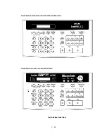
Страница 144: ...V 51 FAX750 FAX770 FAX 910 FAX 920 FAX 921 MFC 925 FAX870MC FAX 930 FAX 931 MFC970MC Key Button Entry Order ...
Страница 150: ...CHAPTER VI ERROR INDICATION AND TROUBLESHOOTING ...
Страница 168: ...July 98 5X4401 Printed in Japan ...
Страница 177: ......
Страница 178: ......
Страница 182: ......
Страница 184: ......
Страница 197: ......
Страница 198: ......
Страница 202: ......
Страница 216: ......
Страница 218: ......

