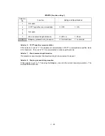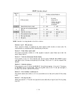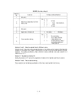
V
- 30
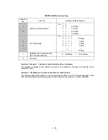
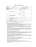
WSW17
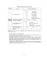
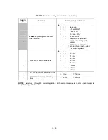
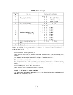
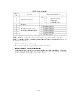
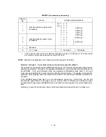
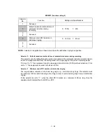
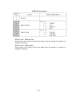
(Function setting 2)
Selector
No.
Function
Setting and Specifications
1
2
Off-hook alarm
No. 1
2
0
0
:
No alarm
0
1
:
Always valid
1
X
:
Valid except when
'call reservation'
is selected.
3
Power failure report output
0:
ON
1:
OFF
4
Calendar clock/prompt alternate
display
0:
NO
1:
YES
5
Calendar clock type
0:
U.S.A. type
1:
European type
6
Error indication in activity report
0:
NO
1:
YES
7
Non-ring reception
0:
OFF
1:
ON
8
Not used.
NOTE:
Selector 3 is not applicable to the U.S.A. versions.
l
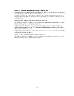
Selectors 1 and 2: Off-hook alarm
These selectors activate or deactivate the alarm function which sounds an alarm when the
communication is completed with the handset being off the hook.
l
Selector 3:
Power failure report output
This selector determines whether or not the equipment outputs a power failure report when the
power comes back on.
l
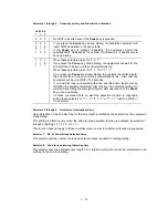
Selector 4:
Calendar clock/prompt alternate display
If this selector is set to "1," the calendar clock and the prompt "INSERT DOCUMENT" appear
alternately on the LCD while the equipment is on standby; if it is set to "0," only the calendar clock
appears.
l
Selector 5:
Calendar clock type
If this selector is set to "0" (USA), the MM/DD/YY hh:mm format applies; if it is set to "1" (Europe),
the DD/MM/YY hh:mm format applies: DD is the day, MM is the month, YY is the last two digits of
the year, hh is the hour, and mm is the minute.
l
Selector 6:
Error indication in activity report
This selector determines whether or not a communications error code will be printed in the activity
report.
l
Selector 7:
Non-ring reception
Setting this selector to "1" makes the equipment receive calls without ringer sound if the ring delay
is set to 0.
Содержание FAX 750
Страница 4: ...CHAPTER I GENERAL DESCRIPTION ...
Страница 11: ...CHAPTER II INSTALLATION ...
Страница 12: ...CHAPTER III THEORY OF OPERATION ...
Страница 14: ...III 1 1 OVERVIEW Not provided on the FAX 910 ...
Страница 24: ...III 11 Active Gears on the Inner Side of the Drive Unit ...
Страница 26: ...III 13 Active Gears on the Inner Side of the Drive Unit ...
Страница 30: ...III 17 Location of Sensors and Actuators 1 ...
Страница 31: ...III 18 Not provided on the FAX 910 Location of Sensors and Actuators 2 ...
Страница 34: ...III 21 FAX750 FAX770 FAX 910 FAX 920 FAX 921 MFC 925 FAX870MC FAX 930 FAX 931 MFC970MC ...
Страница 39: ...CHAPTER IV DISASSEMBLY REASSEMBLY LUBRICATION AND ADJUSTMENT ...
Страница 44: ...IV 4 n n Disassembly Order Flow ...
Страница 48: ...IV 8 4 Disconnect the panel main harness ...
Страница 52: ...IV 12 ...
Страница 70: ...IV 30 Remove the two screws and lift up the paper feed chute ...
Страница 72: ...IV 32 ...
Страница 78: ...IV 38 ...
Страница 86: ...IV 46 1 17 Harness Routing ...
Страница 88: ...IV 48 ...
Страница 89: ...IV 49 2 LF roller ASSY 3 Platen frame ASSY ...
Страница 90: ...IV 50 ...
Страница 91: ...IV 51 4 Separation roller and main frame ...
Страница 92: ...CHAPTER V MAINTENANCE MODE ...
Страница 99: ...V 6 Scanning Compensation Data List ...
Страница 144: ...V 51 FAX750 FAX770 FAX 910 FAX 920 FAX 921 MFC 925 FAX870MC FAX 930 FAX 931 MFC970MC Key Button Entry Order ...
Страница 150: ...CHAPTER VI ERROR INDICATION AND TROUBLESHOOTING ...
Страница 168: ...July 98 5X4401 Printed in Japan ...
Страница 177: ......
Страница 178: ......
Страница 182: ......
Страница 184: ......
Страница 197: ......
Страница 198: ......
Страница 202: ......
Страница 216: ......
Страница 218: ......

