Document: SLSA-MIP-5-4-0-US
Date of Issue: 05/2016
Revision: -
10-7
10.2.1.5
Engine mount
The engine mount connects the power unit to the airplane. It is welded from 4130 steel tubes
and is attached to the firewall and to the engine by means of bolts. The engine mount is
installed on the firewall by four attachments through rubber shock absorbers. The scheme of
engine mount attachment to the firewall and to the engine is shown in the Fig. 10-1.
Fig. 10-1
Rotax engine mount
1 - Firewall
2 - Engine mount
3 - Attachment bolts with shock absorbers
4 - Nyloc nut
10.2.1.6
Engine cowling
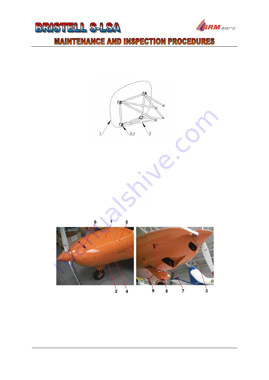
Engine cowling (Fig. 10-2) consists of two parts: upper cowling and lower cowling. The upper
cowling (1) is attached by means of quick fasteners (4) to the firewall and to the lower cowling
(2). Unlock the quick fasteners by turning the bolt by 90° counter–clockwise. The access
cover (5) which is located on the upper cowling on the left side in front of the firewall enables
to check oil quantity in the oil tank without removing the upper cowling.
The lower cowling (2) is attached by means of quick fasteners (4) to the firewall and to the
upper cowling (1). There is in the front part of the lower cowling (2) an oval hole (3) for air
inlet to the oil radiator. In the bottom part of the lower cowling (2) is NACA inlet for air intake
to the water cooler.
Fig. 10-2
Engine cowlings
1 - Engine upper cowling
2 - Engine lower cowling
3 - Air inlet hole for oil radiator
4 - Quick fasteners
5
– Access cover to oil tank
6 - Ram air NACA scoops
7
– Water cooler NACA scoop
8 - Ram air to airbox
NACA scoop
9
– Gascolator hole (optional)
Содержание S-LSA
Страница 2: ......
Страница 12: ...1 CHAPTER GENERAL Document SLSA MIP 5 4 0 US Date of Issue 05 2016 Revision 1 4 Fig 1 1 Three view drawing...
Страница 16: ...1 CHAPTER GENERAL Document SLSA MIP 5 4 0 US Date of Issue 05 2016 Revision 1 8 INTENTIONALLY LEFT BLANK...
Страница 40: ...3 CHAPTER FUSELAGE Document SLSA MIP 5 4 0 US Date of Issue 05 2016 Revision 3 10 INTENTIONALLY LEFT BLANK...
Страница 48: ...4 CHAPTER WING Document SLSA MIP 5 4 0 US Date of Issue 05 2016 Revision 4 8 INTENTIONALLY LEFT BLANK...
Страница 56: ...5 CHAPTER TAIL UNIT Document SLSA MIP 5 4 0 US Date of Issue 05 2016 Revision 5 8 INTENTIONALLY LEFT BLANK...
Страница 98: ...8 CHAPTER LANDING GEAR Document SLSA MIP 5 4 0 US Date of Issue 05 2016 Revision 8 16 INTENTIONALLY LEFT BLANK...
Страница 111: ...10 CHAPTER POWER UNIT Document SLSA MIP 5 4 0 US Date of Issue 05 2016 Revision 10 5 10 2 1 3 Fuel type...
Страница 136: ...10 CHAPTER POWER UNIT Document SLSA MIP 5 4 0 US Date of Issue 05 2016 Revision 10 30 INTENTIONALLY LEFT BLANK...
Страница 160: ...13 CHAPTER VENTILATION HEATING Document SLSA MIP 5 4 0 US Date of Issue 05 2016 Revision 13 6 INTENTIONALLY LEFT BLANK...
Страница 164: ...14 CHAPTER AEROPLANE HANDLING Document SLSA MIP 5 4 0 US Date of Issue 05 2016 Revision 14 4 INTENTIONALLY LEFT BLANK...
Страница 196: ...16 CHAPTER WIRING DIAGRAMS Document SLSA MIP 5 4 0 US Date of Issue 05 2016 Revision 16 10 INTENTIONALLY LEFT BLANK...


