61
Section 5 • Assembly
5 HP Outboard • Troubleshooting & Repair Manual
5
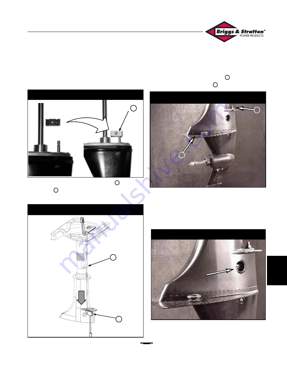
IMPORTANT
: The locating ridges of the clamp must
engage the slot in the rod.
13. Place the shift selector in
NEUTRAL
.
14. Slide the upper shift rod
(Figure 121)
into the
clamp
as you place the gear case onto the
midsection
.
15. Install the gear case assembly to the midsection.
Torque the screw
(Figure 122)
to
60 in. lbs.
(7 Nm)
. Torque the nut
to
80 in. lbs. (9 Nm)
.
16. Verify that the gear lever and gear case are both in
NEUTRAL
, and that the shift rod and shift cam/rod
are both engaged to the clamp. Tighten the clamp
through the hole in the gear case
(Figure 123).
Torque the clamp screw to
35 in. lbs. (4 Nm)
.
Again verify
NEUTRAL
.
17. Use Briggs & Stratton Socket
(#19557)
, to torque
the carrier to the gear case. Torque the carrier to
120 ft. lbs. (160 Nm).
18
19
16
17
Figure 120 — Shift Clamp
Figure 121 — Shift Rod Assembly
Figure 122 — Install Gear Case
Figure 123 — Tighten Shift Clamp
16
16
17
18
19
Содержание 5 HP
Страница 12: ...10 Section 1 Introduction 5 HP Outboard Troubleshooting Repair Manual 1 ...
Страница 14: ...12 Section 2 Troubleshooting 5 HP Outboard Troubleshooting Repair Manual 2 ...
Страница 22: ...20 Section 2 Troubleshooting 5 HP Outboard Troubleshooting Repair Manual 2 ...
Страница 24: ...22 Section 3 Disassembly 5 HP Outboard Troubleshooting Repair Manual 3 ...
Страница 38: ...36 Section 3 Disassembly 5 HP Outboard Troubleshooting Repair Manual 3 ...
Страница 40: ...38 Section 4 Overhaul 5 HP Outboard Troubleshooting Repair Manual 4 ...
Страница 48: ...46 Section 4 Overhaul 5 HP Outboard Troubleshooting Repair Manual 4 ...
Страница 50: ...48 Section 5 Assembly 5 HP Outboard Troubleshooting Repair Manual 5 ...
Страница 68: ...66 Section 5 Assembly 5 HP Outboard Troubleshooting Repair Manual 5 ...
Страница 76: ...74 Section 6 Appendix 5 HP Outboard Troubleshooting Repair Manual 6 ...


