WF2613
Installation
10
3/5/2013
Bradley
•
215-1451 Rev. F; ECN 13-00-001
6
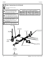
Valve Connections for Infrared
A
Connect the stop-strainer-check valves,
mixing valve, volume control valve and
solenoid valve assembly to the supplies.
Use pipe sealant to seal threads.
B
C
D
For overhead supply lines, install 1/2"
nominal copper supply tubing by passing
the lines through the holes in the dispenser
cover and down through the support tube.
Using suitable fittings, install the
complete valve assembly to the supplies
at the approximate height indicated in
table to the right.
Connect the 1/2" supply tubing from the
sprayhead to the solenoid valve assembly.
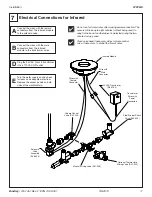
Manual Mixing Valve (S01-038)
Optional Thermostatic
Mixing Valve (S01-525)
Distance to
Finished Floor
(Refer to Table
Above)
Supply
Tubing
Stop/Strainer/Check
Valve (S60-003)
Tailpiece
(129-007)
Washer
(124-001A)
Reducer
Nut (110-005)
Solenoid
Valve
Assembly
(S08-055)
Volume Control
Valve (S02-045)
Flush supply lines before making
connections.
Distance from 1/2" Supply to Finished Floor
Model Number
Type A or O
Type B or H
Standard Height
9" (229mm)
6-3/16" (157mm)
Juvenile Height
5-1/4" (133mm)
3-7/16" (87mm)


