background image

DSS user interface

4–7

1070 066 091-102 (01.08) GB

4.3

Editing/sending *.scs files

*.scs files can be edited and saved in the integrated editor (offline parameter-

ization). 

If  *.scs files have been loaded into the editor, the complete files may be

transmitted to the drive.

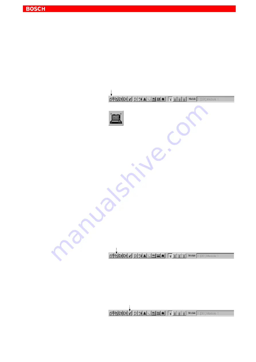
1. Select the desired *.scs file by

D

the menu sequence FILE 

"

 OPEN, or

D

Icon bar: Click on

– or –

D


"

 DSS FILE in the ”Overview” window.

2. Load the selected ”.scs file into the editor by clicking on ”Open”.

Several files may be opened in parallel. Each file will then be displayed in

a separate editor window.

3. Edit the file.

.

For more information on the structure and syntax of *.scs files,

please refer to the DSS help system which you may call up with

HELP


"

 CONTENTS in the ”DSS files” paragraph of the ”Syntax”

chapter.

.

It is also possible to combine several *.scs files with the ”INCLUDE”

command. When contained in a *.scs file, the ”INCLUDE” command

will cause the contents of a specified file to be sent instead of the

line containing INCLUDE when the file is transmitted to the drive.

For more information on the syntax and possible commands in

*.scs files, please refer to the DSS help system which you may call

up with HELP


"

 CONTENTS in the ”DSS files” paragraph of the

”Syntax” chapter.

4. When data has been changed, you may save the file by

D

the menu sequence FILE 

"

 SAVE, or

D

Icon bar: Click on

.

The previous file will be completely overwritten.

If this is not desirable, you have to save the file under a different

name. In this case, you should select the 

menu sequence FILE 

"

 SAVE AS...

5. To transmit the file in the 

active editor window 

to the drive, select

D

the menu sequence EDIT 

"

 SET, or

D

Icon bar: Click on

After transmission, the 7-segment display on the module shows the value

”4”. Now the drive uses this data.

LSA Control S.L. www.lsa-control.com [email protected] (+34) 960 62 43 01

Содержание Servodyn-D Series

Страница 1: ... Rexroth Indramat Bosch y Aventics LSA Control S L Bosch Rexroth Sales Partner Ronda Narciso Monturiol y Estarriol 7 9 Edificio TecnoParQ Planta 1ª Derecha Oficina 14 Parque Tecnológico de Paterna 46980 Paterna Valencia Telf 34 960 62 43 01 comercial lsa control com www lsa control com www boschrexroth es ...

Страница 2: ...Servodyn D with PROFIBUS DP interface Commissioning with DSS Antriebs und Steuerungstechnik Servodyn D 102 Edition LSA Control S L www lsa control com comercial lsa control com 34 960 62 43 01 ...

Страница 3: ... E 2001 by Robert Bosch GmbH Erbach Germany All rights reserved including applications for protective rights Reproduction or distribution by any means subject to our prior written permission Discretionary charge EUR 5 11 LSA Control S L www lsa control com comercial lsa control com 34 960 62 43 01 ...

Страница 4: ... configuration data 3 14 3 4 Cyclic operation 3 16 3 4 1 Telegram structure Motion controlled mode MC mode 3 16 3 4 2 Telegram structure Interpolation in drive 3 17 3 4 3 Telegram structure Velocity control 3 17 3 4 4 Telegram structure Velocity control with actual value feedback 3 17 3 5 Diagnostics 3 18 4 DSS user interface 4 1 4 1 DSS basic image 4 1 4 2 DSS monitor 4 4 4 3 Editing sending scs ...

Страница 5: ...ols 7 3 8 Diagnostics 8 1 8 1 Drive configuration logbook 8 1 8 2 Drive status 8 2 8 3 I O signals 8 4 8 4 Separate window for cyclic display 8 5 8 5 Updating the parameter values of a scs file 8 6 A Annex A 1 A 1 Pin assignment of the PROFIBUS DP interface X51 A 1 A 2 Pin assignment of the RS232 interface at the drive X99 A 1 A 3 Index A 2 LSA Control S L www lsa control com comercial lsa control...

Страница 6: ... 0160 and EN 60146 1 1 VDE 0558 11 D are designed for operation in industrial environments emission class A i e D no direct connection to public low voltage power supply D connection to the medium or high voltage system via a transformer In residential environments in trade and commerce as well as small en terprises class A equipment may only be used if it does not inadmissibly interfere with othe...

Страница 7: ...cal or electronic equipment Interventions in the hardware and software of our products unless de scribed otherwise in this manual are reserved to our specialized personnel Tampering with the hardware or software ignoring warning signs attached to the components or non compliance with the warning notes given in this manual may result in serious bodily injury or material damage Only electrotechnicia...

Страница 8: ...afety markings on products Warning of dangerous electrical voltage Electrostatically sensitive components Lug for connecting PE conductor only Connection of shield conductor only LSA Control S L www lsa control com comercial lsa control com 34 960 62 43 01 ...

Страница 9: ...onal injury DANGER This symbol is used wherever insufficient or lacking compliance with in structions may result in personal injury CAUTION This symbol is used wherever insufficient or lacking compliance with in structions may result in damage to equipment or data files This symbol is used to draw the user s attention to special circumstances L This symbol is used if user activities are required L...

Страница 10: ...hazards Possible retrofits or modifications to the system using third party equipment therefore have to be approved by Bosch DANGER Health hazards through destroyed electrical components Do not destroy any built in components Dispose of destroyed com ponents in a proper manner DANGER Please note your local system specific regulations and require ments as well as the proper use of tools hoisting an...

Страница 11: ...atic discharge ESD D Personnel responsible for storage transport and handling must have training in ESD protection D ESD sensitive components must be stored and transported in the pre scribed protective packaging D ESD sensitive components may only be handled at special ESD work places D Personnel working surfaces as well as all equipment and tools which may come into contact with ESD sensitive co...

Страница 12: ...ssioning manual 1070 066 015 1070 066 035 Servodyn D with PROFIBUS DP Commissioning manual 1070 066 090 1070 066 091 Frequency inverters DM DS 8001 ASM Parameter and commissioning manual 1070 066 008 1070 066 028 Diagnostics maintenance 1070 066 012 1070 066 032 1070 066 062 1070 066 052 RSU Redundant safety monitoring 1070 066 006 1070 066 026 1070 066 081 1070 066 082 EMC manual 1070 066 072 107...

Страница 13: ...fications Modifications in the present manual as compared to the previous edition are marked by black vertical bars in the margin Trademarks All trademarks of software installed on Bosch products upon delivery are the property of the respective manufacturer Upon delivery all installed software is copyright protected The software may only be reproduced with the approval of Bosch or in accordance wi...

Страница 14: ...ion 3 D Adjust optimize all required drive parameter values This has to be done using the DSS The DSS is designed for PCs on which the Windowst operating sys tem has been installed The installation and operation of the DSS requires general knowledge of the Windows user interface e g start exit programs open save files change program windows etc In the present manual we suppose that this knowledge ...

Страница 15: ... Power supply L Turn the 24 V supply on Measure the voltage of the 24V supply at the con nectors It must be between 20 8 28 8 V L Turn the power supply on and measure the voltage It must be between 342 510 V L Turn the power supply and the 24 V supply off Do not proceed unless all connectors terminals are de energized L Plug in all connectors terminals except the PROFIBUS connectors X51 to the inv...

Страница 16: ...void faults and overload a relay must be connected in series Holding brake L Check holding brake for proper functioning if the motor is equipped with a holding brake The holding brake is released when 24VDC are connected The contactor is triggered by the OUT3 output of the inverter In order to avoid faults and overload a relay must be connected in series EMERGENCY STOP circuit L Check for proper f...

Страница 17: ...hexadecimal value The value setting must be unique i e it may be assigned to a single slave in the PROFIBUS environment only S2 S3 Address __ __ hex S2 S3 Address 02 hex Example Baudrate The baudrate set by the master is automatically identified by the drive Maximum baudrate 12 MBaud Mode L Set rotary switch S4 to the value 0 S5 Mode 0 Standard operation F Test mode Connection between master and s...

Страница 18: ...o X99 of the first inverter and record the PC port used For pin assignments and wiring of the RS232 interface X99 please re fer to the annex on page A 1 ff Configuring the interface DSS L Switch on the 24V supply of the system If display H1 of the inverter does not show any of the values 0 2 or 4 check the system as described in section 2 1 L Switch on the PC Wait until the operating system has be...

Страница 19: ...onnection between the PC and the drive and then click on the Retry command button D If the connection can be established the DSS will read information from the drive and then display the Overview DSS window Reinitializing DSS after module RESET or a module change If while DSS is running you D disconnect the connection cable from the inverter e g for starting up a new drive or D press the RESET key...

Страница 20: ...andards IEC 1158 2 Interface type PROFIBUS DP PROFIBUS services Write_Read_Data Data_Exchange Default_SAP Read_Inputs SAP56 Read_Outputs SAP57 Global_Control SAP58 Get_Config SAP59 Slave_Diagnosis SAP60 Set_Param SAP61 Check_Config SAP62 For more information concerning the hardware setting of PROFIBUS interface X51 address mode please refer to page 2 4 Please note that the PROFIBUS address can onl...

Страница 21: ...ging Function First up to 32 blocks consisting of position velocity acceleration and decel eration data are uploaded to the drive by the DSS All block information may also be replaced by the DSS during operation The changes made will not become effective before the next block is selected The following is exchanged cyclically between the master and the drive using the Data_Exchange service in order...

Страница 22: ...ary axis D P 0 2820 MC mode Target positions Weighting S 0 0076 D P 0 2830 MC mode Positioning speed Weighting S 0 0044 if not specified S 0 0259 will be used D P 0 2840 MC mode Positioning acceleration Weighting S 0 0160 if not specified S 0 0260 will be used D P 0 2850 MC mode Positioning delay Weighting S 0 0160 if not specified S 0 0260 will be used D P 0 2860 MC mode Positioning control value...

Страница 23: ...Axis active Block end Acknowledge reset RESET Normal positioning Target change Positioning aborted without target change Start Stop In Position Block selection bit 0 Block selection bit 1 Controller enable Axis active Block end Acknowledge reset RESET Positioning aborted with target change Repeated identical target Moved manually LSA Control S L www lsa control com comercial lsa control com 34 960...

Страница 24: ...ts are inhibited setpoints are effective X X r r X r r X X X r X XX X X 15 0 1 0 X 0 or 1 r reserved 2 1 0 1 Bit 1 Drive enable no drive enable drive has been enabled 0 1 Bit 2 Drive on drive off drive on X Bit 4 New Setpoint Positive edge 0 1 accepts the motion block data to the interpolator and starts the motion 0 1 Bit 6 absolute relative target position input as absolute dimension target posit...

Страница 25: ...on as the current position is within the posi tioning window S 0 0057 or if bit 11 of P 0 2800 becomes high clear distance to go If the distance to go is larger than the position ing window or after an interruption of the motion P 0 2800 bit 8 1 bit 10 becomes low Bit 11 Position limit has been exceeded If the drive has been referenced P 0 2801 bit 9 1 bit 11 of P 0 2801 becomes high if the positi...

Страница 26: ...ferencing parameter D P 0 0006 Type of position encoder motor encoder D S 0 0057 Positioning window fine D S 0 0049 Position limit value positive D S 0 0050 Position limit value negative D S 0 0055 Position polarity parameter D S 0 0076 Type of weighting for position data D S 0 0044 Type of weighting for velocity data D S 0 0160 Type of weighting for acceleration data For more information on these...

Страница 27: ...nts are effective r r r r r r r r r r r r XX X X 15 0 1 0 X 0 or 1 r reserved 2 1 0 1 Bit 1 Drive enable no drive enable drive has been enabled 0 1 Bit 2 Drive on drive off drive on 0 1 Bit 3 Reset diagnostics class 1 no effect reset diagnostics class 1 Bits 0 1 and 2 are high Power is connected The motor is controlled D PROFIBUS status word P 0 2801 Bit 3 Error has ocurred r r r X X X r r r r r r...

Страница 28: ...ve mode the bits are interpreted differently Directly relevant parameters D P 0 2800 PROFIBUS control word bits 0 to 3 D P 0 2801 PROFIBUS status word bits 3 10 to 12 D S 0 0036 Velocity setpoint Weighting S 0 0044 Additional parameters used D S 0 0157 Velocity window D S 0 0044 Type of weighting for velocity data D S 0 0138 Acceleration bipolar D S 0 0160 Type of weighting for acceleration data F...

Страница 29: ...following is exchanged cyclically between the master and the drive using the Data_Exchange service in order to control the drive and for spe cial status messages of velocity control with actual value feedback D PROFIBUS control word P 0 2800 Bit 0 Drive Halt drive halt setpoints are inhibited setpoints are effective r r r r r r r r r r r r XX X X 15 0 1 0 X 0 or 1 r reserved 2 1 0 1 Bit 1 Drive en...

Страница 30: ...r polation in the drive mode the bits are interpreted differently Directly relevant parameters D P 0 2800 PROFIBUS control word bits 0 to 3 D P 0 2801 PROFIBUS status word bits 3 10 to 12 D S 0 0036 Velocity setpoint Weighting S 0 0044 D S 0 0040 Actual velocity value Weighting S 0 0044 D P 0 2816 Actual position value depends on multiplication S 0 0256 with S 0 0256 4 8192 increments per motor re...

Страница 31: ...BUS DP D Set_Param SAP61 D Check_Config SAP62 During this time display H1 at the inverter shows the value 2 Power On Set_Param OK WAIT_PRM yes no WAIT_CFG Set_Param SAP61 Check_Config OK yes no Check_Config SAP62 Data_Exchange Cyclic operation Initialization Display H1 Display H1 Display H1 LSA Control S L www lsa control com comercial lsa control com 34 960 62 43 01 ...

Страница 32: ... Next to the information to be exchanged in cyclic operation the configuration data contain the scope of the input and output data areas as well as specifi cations for the consistency of the data For the structure of the configuration data refer to section 3 3 2 3 3 1 Structure of the parameterization data Byte MSB Bit no LSB Description Type Byte 7 6 5 4 3 2 1 0 Description Type 0 Lock Req Unlo R...

Страница 33: ...egrams required for the individual drive modes is described in section 3 4 on page 3 16 ff MSB Bit no LSB Description 7 6 5 4 3 2 1 0 Description Length of data 0000 1 byte or word 0001 2 bytes or words 1111 16 bytes or words Input output 00 special identification formats 01 Input telegram from slave to master 10 Output telegram from master to slave 11 Input output Format length 0 Byte byte struct...

Страница 34: ...from master to slave 1 2 Identification byte for actual value and setpoint telegrams Identification bytes Velocity control E2H 50H Transmission sequence from master to slave 1 2 Identification byte for actual value and setpoint telegrams Identification bytes Velocity control with actual value feedback E2H D4H Transmission sequence from master to slave 1 2 Identification byte for actual value and s...

Страница 35: ...ou may display on the DSS the data that is exchanged S 0 0024 configuration list for master data telegram contains the numbers of all parameters sent by the master to the slave S 0 0016 configuration list for drive telegram contains the numbers of all parameters sent by the slave to the master In the event of diagnostics messages or errors refer to section 3 5 on page 3 18 ff 3 4 1 Telegram struct...

Страница 36: ...re Velocity control P 0 2801 S 0 0036 Cyclic setpoint telegram Cyclic actual value telegram Master to slave Slave to master Transmission sequence P 0 2800 Output master Input master O 0 I 0 I 1 O 5 3 4 4 Telegram structure Velocity control with actual value feedback S 0 0036 P 0 2816 S 0 0040 P 0 2801 Cyclic setpoint telegram Cyclic actual value telegram Master to slave Slave to master Transmissio...

Страница 37: ... 6 header byte for de vice specific diagnostics contains more information about its structure Byte MSB Bit no LSB Description Type Byte 7 6 5 4 3 2 1 0 Description Type 0 X Station status_1 Bit 3 0 no extended diagnostics information Bit 3 1 extended diagnostics information 1 Station status_2 Stan 2 Station status_3 Stan dard 3 Master address dard 4 Ident number 014A hex 5 Ident number 014A hex 6 ...

Страница 38: ...0 13 Position limit has been exceeded F14 14 15 Manufacturer specific error 0 Speed controller synchronization error 1 Overspeed F15 2 Lag error F12 3 Current controller synchronization error 4 Analog to digital conversion error of current controller 5 VM error F97 6 VM tripped F98 User1 7 Watchdog error F06 User1 8 Option module error 9 Personality Module error 10 DSP program starts too early F90...

Страница 39: ...terface F70 6 Number of encoder divisions not defined F70 Encoder 7 I2C bus initialization error F70 Encoder 8 Errror when reading via I2C bus F70 9 Incorrect number of encoder divisions F70 10 Encoder parameter has the value 0 F70 11 Timeout when reading via EnDat interface F70 12 Encoder interface not available F70 13 Error in EnDat data transmission F70 14 Error function of EnDat measuring syst...

Страница 40: ...iagnostics class 1 Indication Description Bit 0 Initialization error Profibus PRM P01 1 Initialization error Profibus CFG P02 2 3 4 5 6 PROFIBUS 7 PROFIBUS 8 9 10 11 12 13 14 15 LSA Control S L www lsa control com comercial lsa control com 34 960 62 43 01 ...

Страница 41: ...PROFIBUS DP interface 3 22 1070 066 091 102 01 08 GB Notes LSA Control S L www lsa control com comercial lsa control com 34 960 62 43 01 ...

Страница 42: ...ions of more than 800 x 600 pixels unless you have at least a 17 monitor Menu bar Icon bar Status bar Dialog area for displaying DSS specific win dows and dialogs shown Overview window 1 2 1 Changes the DSS program window and exits the program 2 Changes a DSS specific window Please note that iconized window symbols may be covered by open win dows Covered windows can be displayed by selecting the W...

Страница 43: ...or to the selected module switches automatic correction on off switches the transmission mode single step on off only effective with open scs file replaces an open and selected scs file after changes When the mouse pointer is placed on a symbol its function is shown for a moment in plain text Recessed symbols signal the status function activated Status line Active interface Parameter currently or ...

Страница 44: ...splays a pulldown menu from which component specific commands functions can be called up Monitor edit parameters on line Load file edit parameters off line DSS expert Parameterization Motion control no func tion with PROFIBUS DP interface Setpoint input Interface Module x Setpoint box Setpoint generator Increment Reset phase Select interface DSS Reset Cyclic telegram Reset device error Load Save m...

Страница 45: ...e changed Current changeable parameter number Current changeable pa rameter value When the Data text appears dimmed the data cannot be changed Input limits of the current parameter Parameter list Double click on one of the parameters to dis play its information in the upper fields Read current pa rameter from the drive Transfer current parameter to the drive Parameter change becomes immediately ac...

Страница 46: ...mand page 4 13 All parameters that have been read will be automatically entered in the pa rameter list and sorted according to their ident numbers A parameter list can be saved in a scs file using the Export function To delete parameters from the list click on the list line in question and press Del key Parameter lists By clicking on the Import command button all parameters of a scs file are impor...

Страница 47: ...n be accepted to the upper fields as current value Whether or not the DSS is to read the parameter again from the mod ule can be configured by selecting the Reload with double click checkbox on the Global tab of the EXTRAS PREFERENCES menu To read all parameters in the list again mark the All ID no s check box and confirm by clicking on Get 2 When they have been changed the parameters can be trans...

Страница 48: ...s with the INCLUDE command When contained in a scs file the INCLUDE command will cause the contents of a specified file to be sent instead of the line containing INCLUDE when the file is transmitted to the drive For more information on the syntax and possible commands in scs files please refer to the DSS help system which you may call up with HELP CONTENTS in the DSS files paragraph of the Syntax ...

Страница 49: ...IT SINGLE STEP or D Icon bar Click on Single step is active The symbol is shown recessed Automatic correction Ident numbers rejected by the drive with the error message currently write protected will be transmitted again after the next phase change over con tained in the file The Automatic correction function can be activated deactivated by D the EDIT AUTOMATIC CORRECTION or D Icon bar Click on Au...

Страница 50: ...mand button to confirm your selection To activate the new language you have to restart the DSS Language of the drive The language of the parameter diagnostics texts in the drive is defined in pa rameter S 0 0265 The languages listed in S 0 0266 may be selected D 0 German D 1 English corresponds to English language L Enter the numerical value of the desired language in the Data field Pressing Retur...

Страница 51: ...his field are still shown in the previously selected language Name of parameter in plain text cannot be changed The new setting will only remain active until you switch off the drive or press the RESET button on the inverter To switch the drive permanently to the new language you have to perform the Save main memory command cf page 4 13 LSA Control S L www lsa control com comercial lsa control com...

Страница 52: ...es D D The Service user group is password protected The corresponding pass words are available on request L Select EXTRAS PREFERENCES Access tab current user group category character inputs are dis played as CAUTION Unauthorized access to protected functions possible If you have changed the user group to Service you should com plete the necessary operations and restart the DSS or reset the sys tem...

Страница 53: ...red phase before changing such parameters If you forget changing phases an error message of the type Data of parameter x 0 xxxx is write protected at this time will usually be output You may change to the higher next phase by D Menu sequence CONTROL INCREMENT INITIALIZATION PHASE or D Icon bar Click on or D INCREMENT INITIALIZATION PHASE in the Overview window You may change back to phase 0 by D M...

Страница 54: ...set and optimized during ini tial commissioning can be used for another drive only series commis sioning if a backup was made refer to section 5 3 on page 5 10 CAUTION Save main memory cannot be reversed All data contained in the FEPROM will be replaced with the current data If you are not sure whether you still need the old FEPROM data please contact your systems administrator before executing th...

Страница 55: ...ry of the drive is overwritten All data in the RAM will be replaced with the parameters contained in the FEPROM by the Load main memory command This process cannot be reversed If you are not sure whether you still need the old RAM data please contact your systems administrator before executing this command L Switch the drive to phase 2 L Select the menu sequence D CONTROL LOAD MAIN MEMORY or D LOA...

Страница 56: ...eset the error in the DSS open the logbook for diagnostics class 1 errors cf section 8 1 The error history is listed by the error codes in the logbook Alternatively open the Module error display by D menu sequence DIAGNOSTICS MODULE ERROR DISPLAY or D Icon bar Click on Locate the cause of the error and eliminate all errors Then enter the com mand Reset device error by D Menu sequence CONTROL RESET...

Страница 57: ...DSS user interface 4 16 1070 066 091 102 01 08 GB Notes LSA Control S L www lsa control com comercial lsa control com 34 960 62 43 01 ...

Страница 58: ...mbers are of relevance for the basic parameter setting For a detailed description of the following parameters please refer to the Servodyn D parameter manual Functionality Relevant parameters Default value Your value Operating frequency of the power output stage A low operating frequency increases the available electrical output power It must be set according to the selected motor module combinati...

Страница 59: ...gnals will first activate the torque depending on P 0 0505 Plug brake enable delay D The drive will not follow the setpoint input before the Waiting time drive on has elapsed Waiting time drive off prevents the axis from jerking caused by the re moval of the torque while the holding brake has not yet engaged S 0 0206 Waiting time drive on changeable in phase 3 4 S 0 0207 Waiting time drive off cha...

Страница 60: ...6 2 Otherwise adjust your basic parameter setting accordingly Without Save main memory the modified parameters will only re main active until you switch off the drive or press the RESET button on the inverter L For data protection you should now save all EPROM parameters in a scs file using the IDN Backup function The default directory used for data backups can generally be changed in the Global t...

Страница 61: ... determination of the absolute dimension offset S 0 0177 L Turn the power supply of the drive on Enable the drive with a zero setpoint The drive is stopped the torque is active L Move the axis to the mechanical zero position L Select EXTRAS DRIVE FUNCTIONS INIT ABSOLUTE ENCODER L Click on Start L Click on No to abort the function Clicking on Yes will start the measurement After the measurement the...

Страница 62: ...ot be influenced They are permanently assigned to the following functions OUT2 Temperature warning OUT3 Control of a holding brake OUT4 Control of a plug braking process L In order to set the parameters of the digital inputs or outputs switch the drive to phase 2 L Load parameters P 0 2000 inputs and P 0 2002 outputs into the monitor L Assign a list containing the desired parameter numbers to the ...

Страница 63: ...ts IN4 IN3 IN2 IN1 P 0 2000 1 Par 2 Par 3 Par 4 Par Gaps in the signal configuration should be filled with S 0 0000 Example 1 If only IN3 is to be assigned program P 0 2000 as follows P 0 2000 0 0 Par L Execute the Save main memory command cf section 4 6 2 LSA Control S L www lsa control com comercial lsa control com 34 960 62 43 01 ...

Страница 64: ...features responds contents of S 0 0333 or S 0 0334 becomes HIGH the drive internally responds by setting certain bits in parameter S 0 0013 diagnostics class 3 Further reactions such as reduction of torque or speed retract move ments EMERGENCY STOP have to be initiated externally by the high er level control unit L Adjust the limit values for torque monitoring to your requirements L Assign paramet...

Страница 65: ...at the load bit 6 in S 0 0044 S 0 0076 and S 0 0160 L Specify the input and output speeds of an interconnected gearbox if any Only integers are permitted here Example The transmission ratio is Ratio 1 128 18 First you have to eliminate the decimal places Ratio 100 12818 by multiplication with 100 or Ratio 50 6409 by multiplication with 50 Enter calculated values in S 0 0121 and S 0 0122 S 0 0121 1...

Страница 66: ...5 ms cycles Each output converts the respective parameter value via a linear character istic into a 0 10 V analog voltage L Select EXTRAS DRIVE FUNCTIONS ANALOG I O ANALOG OUTPUTS Max value fields P 0 2012 to P 0 2015 define for which value 10 V are output IDN fields P 0 2010 determine the parameter value to be output at the corresponding output Offset fields P 0 2012 to P 0 2015 define for which ...

Страница 67: ...hase 4 then reads all pa rameters stored in the FEPROM and saves them in the previously specified file An exception are driver files and the data of the electronic rating plate L Create a suitable directory structure on the hard disk drive of your PC to which you can copy all parameter files of the drive For example you could establish a hierarchy that adequately represents in dividual machine typ...

Страница 68: ...when setting the basic parameters cf page 5 1 ff D generated when programming the extended parameters cf page 5 4 ff D generated during controller optimization cf page 7 2 ff L If you have created scs files for the individual commissioning steps using the IDN Backup function you only have to transfer the scs file that was created last because IDN backup always saves all parameters contained in the...

Страница 69: ...lay on the module shows the value 4 Now the drive uses this data 4 Close the active editor window and transmit the remaining scs files if any 6 2 Couple next drive L Remove the connection line from X99 and plug it to X99 of the next axis mod ule to be commissioned L Reinitialize the DSS D menu CONTROL DSS RESET or D Icon bar Click on LSA Control S L www lsa control com comercial lsa control com 34...

Страница 70: ...eters and experience in the optimization of servo loops The following block diagram is designed to give you an overview of the pa rameters of the servo loop Speed controller Rejection filter low pass filter Current controller PWM output Actual speed value Actual current value P component S 0 0100 Integral action component of speed controller S 0 0101 Speed limit value S 0 0091 Acceleration limit v...

Страница 71: ...ized low pass fil ter Activate low pass filter with maximum transition fre quency cf sect 7 1 2 no yes Optimized rejection circuit Determine rejection frequency Activate rejection circuit Increase filter quality Optimize rejection frequency cf sect 7 1 2 Motor vi brating Reduce P component of speed controller S 0 0100 to approx 2 3 no yes no yes S 0 0100 sufficient End L Execute the Save main memo...

Страница 72: ... In order to process the parameters of the Speed controller and Band stop filter thematic areas click on the area in question and select EDIT from the pop up menu Detailed information speed controller 0000 0 L Double click on the input field to be modified and enter the desired values The Parameter info field now shows the parameter name and the admissi ble input range Apply transfers the current ...

Страница 73: ...he se lected filter type input fields are displayed for configuration L Click on the radio buttons in order to define the filter type or deactivate indi vidual filters L Double click on the input field to be modified and enter the desired values The Parameter info field now shows the parameter name and the admissi ble input range Apply transfers the current values to the drive They will become im ...

Страница 74: ...mation from the drive when the module configuration display is called up Example of the configuration display for a drive with an analog interface 1 Logbook In the Logbook area you may display the last 16 DSS errors and Class 1 errors at any time DSS errors communication errors between the DSS and the drive The error list contains the parameter number that experi enced the error during transmissio...

Страница 75: ...ameters S 0 0011 to S 0 0013 Displaying cyclic data L Select the menu sequence D DIAGNOSTICS MODULE STATUS DISPLAY or D MODULE STATUS DISPLAY in the Overview window Drive status in plain text as per S 0 0095 Display of max 4 parameters For configuration cf page 8 3 For displaying parameters in sepa rate windows refer to section 8 4 page 8 5 Display of 4 digital outputs P 0 2003 For configuration c...

Страница 76: ...arameter in the fields only those pa rameters make sense whose value changes with time CAUTION The PC may respond very slowly to user activities Times that have been selected too short in the Update period field may lead to a very slow response especially if slow computers are used You should not use times of less than 2000 ms unless particularly fre quent updates of the display are absolutely nec...

Страница 77: ... an analog interface Display showing all input sig nals configured in P 0 2000 The current status of the sig nals is derived from P 0 2001 Display showing all output sig nals configured in P 0 2002 The current status of the signals is derived from P 0 2003 A HIGH level is indicated by a green LED a LOW level by a gray LED by the DSS LEDs not followed by a text indicate that the corresponding bit h...

Страница 78: ...rogress bar has been selected the desired upper and lower limit may be specified for calibra tion purposes Display as value Display as value and as progress bar Result Result L Clicking on OK will close the DSS dialog and display the parameter cycli cally in a separate window The data display is updated in the intervals set for the Module status dis play cf page 8 3 Parameter values e g setpoints ...

Страница 79: ...ferences between parameters of different drives L First you should create a complete scs file as a template and save this file When filling in this template the system will only consider the values of the parameters contained in the template L Select the menu sequence FILE FILL TEMPLATE 1 2 L Click on 1 in order to select the template file Only the parameters contained in this file will be read fr...

Страница 80: ...ceive transmit data N Repeater control signal Data reference potential M5V Power supply positive P5V Plug A 2 Pin assignment of the RS232 interface at the drive X99 Cannon connector 9 pole Type RS232 Cable length max 15 m Cable type screened min core cross section 0 14 mm2 Transmission rate 9600 bit s Parameters even parity 8 data bits 2 stop bits Handshake software handshake XON XOFF 1 2 3 RX TX ...

Страница 81: ...etting 4 15 ESD Electrostatic discharge 1 6 grounding 1 6 workplace 1 6 ESD sensitive components 1 6 Establish connection Drive DSS 2 5 Exit the DSS program 4 1 F Feedrate constant 5 8 FEPROM Backup 5 10 7 2 copy to the RAM 4 14 Filling in a template 8 6 Filter configuration 7 4 Firmware version 8 1 Floppy disk drive 1 7 G Gear box 5 8 Grounding bracelet 1 6 H Hard disk drive 1 7 Holding brake Che...

Страница 82: ...on 2 4 Protection against unauthorized interventions 4 11 Q Qualified personnel 1 2 R Release 1 7 RESET 2 6 S Safety instructions 1 4 Safety markings 1 3 Saving all data 5 10 scs file edit 4 7 send 4 7 transmit to drive 6 1 Selecting the language 4 9 Series commissioning 6 1 Loading files 6 1 Signals I O 8 4 Software version 8 1 Spare parts 1 6 Speed controller 7 3 T Temperature warning via OUT2 5...

Страница 83: ...Annex A 4 1070 066 091 102 01 08 GB Notes LSA Control S L www lsa control com comercial lsa control com 34 960 62 43 01 ...

Страница 84: ...stechnik Postfach 11 62 D 64701 Erbach Fax 49 0 60 62 78 4 28 1070 066 091 102 01 08 GB HB AN BRC ESM11 Printed in Germany USA Robert Bosch Corporation Automation Technology Division Fluid Power Products 7505 Durand Avenue USA Racine Wisconsin 53406 Fax 414 5 54 81 03 Robert Bosch Corporation Automation Technology Division Factory Automation Products 816 East Third Street USA Buchanan MI 49107 Fax...

Отзывы: