background image

1)

Mo ve the joy stick up and dow n to select betw een alarm
areas (1-128). 8 alarm areas display o n each page . When
user moves the joystick to the top or the end of the page and
still move s the joystic k up or down, the sy stem turns to the
previous or next page automatically.

2)

Afterselecting alarm area, turn the joystick clockwise to enter
the arming /disarming time setting.

3)

Move the joystick left and right to select between data items.

Move the joystick up and down to set the data or input data
by using the keyboard numeric keypad.

4)

After completing the setting turn the joystick anticlockwise to
exit. If the re is need to set other alarm area, repe at the
above steps.

5)

If there is no other setting, turn the joystick left to return to

higher level menu.

AREA: alarm area sequence number.

START: the time to arm an alarm (24H).

END: the time to disarm an alarm (24H).

EXAMPLE: To arm an alarm at 13:00 the first day and disarm it
at 9:30 the second day on alarm area 001, the operation is
as follows:

Enter the AUTO ALARM SETUP submenu, move the joystick up
and down to select alarm area 001, or just press 1 using the
numeric keypad. Turn the joystick clockwise to enter START
ite m, input 13:00 using the numeric keypad or move the
joystick up and do wn to select data. Mo ve the joystic k to
enter END item, input 09:30. Turn the joystick anticlockwise to
return to the AREA item, move the joystick up and down to
se le ct ano ther A REA num be r. A fter co mple ting all the
ope ration, move the joy stic k left to return to highe r le vel
menu.

9.8 Alarm Control

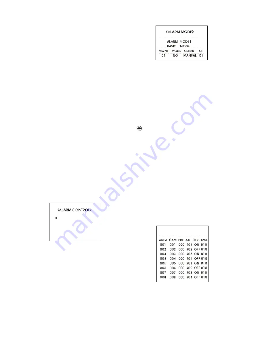
Ente r ALARM CONTROL subm enu as picture 9-8-1 shows. It
includes the items of ALARM MODE, ALARM EXPORT, SENSOR
CONFIG and MESSAGE.

1)

To select one item in the submenu, move the flashing cursor
to the item to be selec ted, move the joystick right to enter
the setting of the item or just input the item number using the
numeric keypad.

2)

If there is no need to edit any item, move the joystick left to

re turn to highe r le vel me nu; input 0 using the numeric
keypad or move the flashing cursor to 0.EXIT and move the
joystick right to exit.

1.    Alarm mode

Enter ALARM MODE submenu as picture 9-8-2 shows.As men-
tioned before, there are three kinds of alarm display modes:
BASIC MODE, AUTO-BUILD, SEQUENCE DISPL.

The setting is as follows:

1)

After enteringthe Alarm Mode item, move the joystick up and

down to select the desired mode.

2)

After sele cting alarm mode, turn the joystick clockwise to

display the detailed setting list of each mode. Move the
joystick left and right to select between the data items. Move
the joystick up and down to set the data.

3)

Turn the joy stic k anticloc kwise to return to A LARM MO DE

selecting menu.

4)

If there is no other setting, move the joystick left to return to the

higher level menu.

NO TE: MO N 1 & MO N 2 de sig nate th e m o nit o rs to
display the alarm vide o s , and num be rs be lo w are
the m o nito r se que nc e num be rs. CL EA R de signate s
the m o de o f c le aring an alarm (MA NUA L o r A UTO ).
KB d e signat e s the ke y bo a rd that has t he righ t to
c le ar the alarm .

2.    Alarm output

Enter ALARM EXPORT submenu as picture 9-8-3 shows.

The following list is for programming or editing alarm output
control. Alarm output control is to control the ope rations of
dome cameras in the alarm area and the driving of periph-
ery equipments when there is alarm event happening.

AREA: alarm area sequence number (1-128).

CAM: camera number (1-128).

PRE: the preset number of cam era (0-100, 0 designates the
current video).

AX: relay number (R1-R4).

CTRL: driving mode of the relay (ON, OFF)

DWL: time of response.

The setting procedure is as follows:

1)

After enteringthe ALARM EXPORT submenu, move the joystick

up and down to select between the alarm area numbers (1-
128). Turn the jo ystick clockw ise to enter the alarm output

ALARM EXPORT

Picture 9-8-3

------------------------------

Picture 9-8-1

1. ALARM MODE

2. ALARM EXPORT

3. SENSOR CONFIG

4. MESSAGE

0. EXIT

Picture 9-8-2

Содержание DR-3207

Страница 1: ......

Страница 2: ......

Страница 3: ...Setup 10 Keyboard Operations 10 1 Video Switching Control 10 2 Pan tilt Control 10 3 Lens Control 10 4 Alarm Control 10 5 Alarm Event 10 6 Acknowledge Alarm Signal 10 7 Screen Characters Display Control 10 8 Call Macro Command 11 Error Messages 12 Appendix 12 1 Keyboard Command Table For Dome 12 2 Keyboard Connection 12 3 Keyboard Command Table for Matrix 17 18 19 21 22 23 23 24 24 25 26 28 28 29 ...

Страница 4: ...Do n ot dr op m et all ic p art s in to th e ve nti la ti on openings Droppingparts willleadto unit malfunction If this does happen switch off the power and notify qualified engineer to service the unit Do not open or remove covers yourself Opening or removing coversmay expose you to dangerous voltage or other hazards There is no user serviceable part Only qualified engineer can service the unit H...

Страница 5: ...user The video switch speed is independent and settable 3 4 Salvo Switch The system can switch multiple videos to different monitors for display simultaneously The system has up to 16 groups of salvo switches and each group has up to 64 steps The dwell time of videos is programmable and the videos can be pre sets ofcameras The system has SYSTEM SALVO SETUPmenu to set the program 3 5 Standard Seque...

Страница 6: ...on the monitor Under the automatic clearance mode the user can also clear the alarm manually 2 Manual clearance under the manual clearance mode the alarm video remains on the respondent monitor untilthe user visits the monitor through the keyboard The master can set and authorize any keyboard the right to clear alarms unau thorized keyboard can not clear the alarms 3 14 Lock Functions To reinforce...

Страница 7: ...priority 4 relay outputs normal open normal close modes 30VAC 0 6A resistance load can extend to 20 outputs S N Ratio weighted 52db Alarm Display 3 selectable displays Differential Gain 0 6 Alarm Outputs Automatic Switch Differential Phase Insert Gain 1 1 0 5db RS232 Port RS485 Port 9 pin D Sub connector Adjacent Channel Isolati on Degree Input to Input Adjacent Channel Crosstalk Input to Output K...

Страница 8: ...de different videos of 128 cameras The dwell time of each step can be programmed and the video can be the preset of a camera It is to memorize the parameters of focus zoom pan tilt angle of a camera video When necessary the preset can be recalled It is to display the programmed preset It is to activate the preset tour It is to delete the preset tour It is to switch any video of any camera to be di...

Страница 9: ...ate setting operation is similar to time setting Descriptions Functions 1 1 Arm disarm alarm Alarm Functions User Functions Alarm display mode Adjust character position Adjust character brightness Set time Set date Set date format Set camera title Set monitor title Set dome camera protocol Set channel status 10 RS232 The system can be connected with PC through a 9 pin D Sub RS232 connector The inf...

Страница 10: ......

Страница 11: ...ht indicates that there is alarm event happening 3 STATUS flashing light indicates that the system is running normally 4 CODEOUT flashing light indicates that the system is sending codes out or receiving codes 6 2 Connection Refer to picture6 2 5 EXTEND the two ports are for extension to parallel connections with other matrixes The connector is RJ 11 Refer to Picture 6 3 forprofile and refer to Fo...

Страница 12: ...ch is for communication matching impedance setting In the communication process when the communi cation distance is too long or the internal resistance of trans mitting line is too large abnormal communication will arise Now user should connect the matching impedance to the communication equipments Switch bit 1 bit 2 bit 3 are not in use now and should be set as OFF Switch bit 4 is set as ON the e...

Страница 13: ......

Страница 14: ...he polarities in the connection must be correct refer to Picture 6 7 for polarity indication 4 The dome ID address must be the same with its video input port number of the matrix the numbers are silkscreened on the back panel ofthe matrix For example when one dome is connected to the video input port number 1 in the matrix the ID address of the dome must be set as 1 7 2 Video Output Connection Con...

Страница 15: ... addresses 1 or 2 port no 2 has the corresponding keyboard ID addresses 3 or 4 port no 3 has the corresponding keyboard ID addresses 5 or 6 portno 4 has the corresponding keyboard ID address 7 or 8 7 4 Extended Keyboard Connection Configuration Note pay attention to the following when conducting ex tended keyboard connections 1 Each matrix keyboard can only connect one extended keyboard 2 Connect ...

Страница 16: ...only be connected to the video from the cam era with the same number as its ID address 7 6 Alarm Input Connection Configuration Note pay attention to the following when conducting alarm input connections 1 Each matrix has 32 built in alarm inputs can be extended to 128 inputs Two alarm modes of Normal Open and Normal Close are available 2 Each alarm detector must be connected toan alarm signal tra...

Страница 17: ...k panel of the matrix Video Recorder Alarm Bell Alarm Light Auxiliary Equipment Relay Output A Line Relay Output B Line Relay Output C Line DR 3207 Marix 3 Each device is connected to relay output B line This is be cause when the system is in normal working condition relay output B line is connected to relay output C line and relay output B line is disconnected to relay output A line When there is...

Страница 18: ... 57 R01 R02 R03 R04 R11 R12 R23 R24 ALM 34 ALM 33 1 2 3 4 ALM 32 ALM 9 ALM 8 ALM 7 ALM 1 ALM 2 1 2 7 8 9 32 NC NC NC 1 2 3 7 MONITOR 1 MONITOR 2 MONITOR 3 MONITOR 7 Main Matrix Subsidiary Matrix Video Output Port Video Output Port Camera Input Port Camera Input Port Alarm Input Port Alarm Input Port Alarm Output Port Alarm Output Port 1 Two Matrixes are to be connected ...

Страница 19: ...t Alarm Input Port Alarm Input Port Alarm Output Port Alarm Output Port Alarm Output Port Monitor x Connecting x monitor NC Connecting none Camera N Camera s ID also is the number of the matrix alarm input port 2 Three Matrixes are to be connected Note pay attention to the following when conducting the parallel connection between matrixes 1 Upto 5 matrixes can be connected in the system with paral...

Страница 20: ...the system refer to 9 1 System Setup for password setting operation If necessary system master can clear users password refer to 9 1 System Setup for password clearance operation User registers with the system after the keyboard is powered up the LCD displays SYSTEM PASSWORD input the password given by the system master to enter the system User changes password press SHIFT OPEN keysand change the ...

Страница 21: ...SYSTEM MENU Joystick to move the cursor to the desired item move the joystick right to enter the setting ENTER key to confirm the operation or selection Numeric keypad to input digits to select desired items Exit SYSTEM MENU Press 0 or move the cursor to 0 EXIT and move the joystick right to exit SYSTEM MENU The SYSTEM MENU has the following 9 items SYSTEM SETUP TOURS SETUP CAMERASETUP MONITOR SET...

Страница 22: ...tup of the items as CAMERA KEYBOARD EXTEND RS232 1 Move the joystick up and down to let the flashing cursor point at the desired item Turn the joystick clockwise to enter the setting or just input the item number by using the numeric keypad to enter the setting 2 After entering the setting move the joystick up and down to set the data 3 Turnthe joystick anticlockwise toexit the setting If there is...

Страница 23: ...l the system will dis play PASSWORD UPDATE SUCCEED and return to the higher level menu automatically If not successful the system will display PASSWORDUPDATEFAIL and the menu still remains in the password setup page 3 To set other passwords repeat the above steps If there in no other setting move the joystick left to return to the higher level menu User can also press 0 or move the cursor to 0 EXI...

Страница 24: ... all the steps remain unchanged The inserted STEP0006 has the original data as 0006 STEP 000 CAM 000 DWELL 000 PRE so the user should set the CAM DWELL PREdata After the insertion the LENGTH number will be changed by adding 1 6 Delete a step move the cursor to the step that is to be deleted For example to delete STEP0005 just press PREV key on keyboard for more than 2 seconds The 4 steps be fore t...

Страница 25: ......

Страница 26: ...t functions The MACRO FUNCTION can set as TOUR AUTO PAN PATTERN NO_ACT or END_ACT Their meanings define as follows TOUR run Tour No 1 AUTO PAN run Auto Pan PATTERN run Pattern No 1 NO_ACT no action END_ACT stop running MACRO FUNCTION The actions run by TOUR AUTO PAN or PATTERNshould be set previously and run at least one time The speed of running TOUR or AUTO PAN is same as the speed of the latest...

Страница 27: ... 9 5 3 designates that for a certain camera No 1 keyboards 1 4 6 have the right level 3 to control keyboards 2 5 7 have the right level 1 to control and keyboard 3 8 have the right level 2 to control 1 No right of access to the dome camera 2 Has right of access to the video only 3 Has right of access to the video and control of the dome camera 3 Keyboard priority setup Enterthe KEYBOARDPRIORITY su...

Страница 28: ... input the item number using the numeric keypad 2 If there is no need to edit any item move the joystick left to return to higher level menu input 0 using the numeric keypad or move the flashing cursor to 0 EXIT and move the joystick right to exit 1 Alarm mode Enter ALARM MODE submenu as picture9 8 2 shows As men tioned before there are threekinds of alarm display modes BASIC MODE AUTO BUILD SEQUE...

Страница 29: ...rming disarming information is of the latest 1000 operations The information includes the alarm area number date and time of each arming disarming operation 3 The recorded alarm events are of the latest 1000 ones The recorded information includes alarm area number date and time of each alarm event 9 9 Salvo Switch Setup Enter the SYSTEM SALVO SETUP menu as picture 9 9 1 shows The list is for progr...

Страница 30: ...be STEP0006 After the insertion the LENGTH number will be changed by adding 1 6 Delete a step move the cursor to the step that is to be deleted For example to delete STEP0005 just press PREV key on keyboard for more than 2 seconds The 4 steps be fore the original STEP0005 remain unchanged The step numbers after the original STEP0005 will be changed by decreasing 1 The LENGTH number will be changed...

Страница 31: ...he operation is Press SHIFT 3 SCAN 3 Stop camera sequential scan OPERATION press SHIFT 0 SCAN 4 Previous camera To display the previous camera video by ID number sequence press PREV 5 Next camera To display the next camera video by ID number sequence press NEXT 6 Salvo switch To run the programmed salvo switch the operations are as follows 1 Set dwell time OPERATION Press SHIFT X DWELL X dwell tim...

Страница 32: ......

Страница 33: ... now being used to display salvo switch standard sequence switch or camera sequential scan and if there is an alarm event coming the monitor will stop the switch display imme diately and turn to display the alarm video 3 When any user is setting the program and if there is an alarm event coming the setting will be stopped immediately 4 The system records the area numbers time and dates of all alar...

Страница 34: ...er with higher priority Please wait Error No 05 Invalid camera request The camera number entered is not registered and does not exist Error No 06 Camera access right transferred The access right of the camera is transferred to a user with higher priority Please wait Error No 07 Invalid monitor request The monitor number entered from keyboard is out of range allowed by the system Error No 08 Invali...

Страница 35: ...85 Bus A2 B2 If Bit8 is set as ON termination impedance is connected to RS485 Bus A3 B3 NOTE Switch power off before the above settings 2 RS485 connection port 3 groups of RS485 output A1 B1 A2 B2 A3 B3 A2 B2 is for controlling dome Dome Commands 3 Power port It is for DC9V power supply connection Refer to Picture 2 for the polarity position NTOE Wh en the matrix k eyboard is conn ected to the m a...

Страница 36: ... Password Change Change password SHIFT OPEN Alarm response 255 ALARM Log out User logs out SHIFT CLOSE All Alarms Acknowledgement 12 3 Keyboard Command Table for Matrix ...

Отзывы: