32
DuraSweeper
®
i.
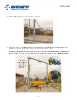
The motor side of the Brush Carriage Assembly may ride about an inch lower
than the other side due to the added weight of the motor. It’s a good idea to
balance this height difference.
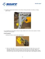
This can easily be done by adjusting the Cable Take-up
Mechanism. To do this, manually raise the unit up about 24” from the bottom and loosen the
Cable Take-up Mechanism until both sides are exactly the same height from the base plate.
The Cable Take-up Mechanism will only raise or lower the side on which the Mechanism is
located. Once the adjustment is completed, firmly jam both nuts against the welded bracket to
lock the Cable Take-up Mechanism in place.
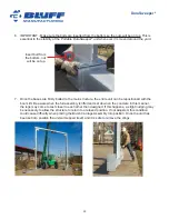
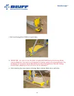
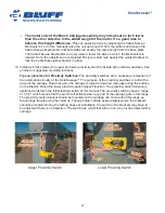
19. Install (with tek screws) the upper and lower proximity switch brackets with proximity switches. See
photos for suggested mounting locations.
Tips on placement of Proximity Switches:
The proximity switches are a necessary component of
the automation circuitry of the DuraSweeper
®
. The purpose of the proximity switches is to limit the
travel of the carriage. Note that when the carriage is raised or lowered manually (using the buttons
on the Electric Panel) the lower proximity switch doesn't function. The proximity switch function is
explained in detail in the initial testing section of this manual. The proximity switches have a range
of 1-1/2", which means that the switch will activate when any part of the carriage gets in this range.
The proximity switch bracket should be mounted so the carriage can come within this range as
the carriage travels along the columns. These photos indicate approximately where the brackets
should be located. During the testing phase of installation, the switch or the brackets may have to
be adjusted if there is no detection. The switch has a light that will turn on, when it has detected the
carriage.
Upper Proximity Switch
Lower Proximity Switch

