Fornacher Strasse 12
Tel43 (720) 010 188
A-4870 Vöcklamarkt
Email:
Austria
www.bluesky-energy.eu
January 10, 2020/greenrock-heimspeicher_installations- & inbetriebnahmehandbuch_v02_en
28
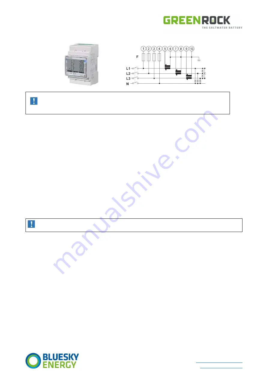
Electrical connection diagram EM330
IMPORTANT
Always pay attention to the direction of energy flow when installing the energy meter.
7.4.3
Communicative integration of the energy meters
GREENROCK EMS has two independent BUS connections. Energy meters are always connected to BUS-1 (RS485).
The communicative integration takes place via RS485 communication between the energy meter and GREENROCK EMS.
It is recommended to use shielded, twisted-pair cables for the RS485 bus cabling.
Example:
Network cable CAT6/7. A twisted pair of wires for A and B is to be used. The max. permissible cable length is 200 metres.
The cables used for energy meters must be twisted and shielded in pairs. In your own interest, please always provide a few
conductors as a reserve for cross-building cabling!
When cabling several energy meters, it is sometimes necessary to use auxiliary terminals for the cabling. These auxiliary terminals
must not be more than 10 cm away from the actual terminal point.
The earth connection of the screen can be carried out in the following ways:
Joint earth connection
Connect the shields of the incoming and outgoing cables and earth all shields together at only one end of the data line.
Separate earth connection
Earth each screen on only one side of the cable.
The shield and unused wire pairs must not be connected to the GND connections (neither on the devices nor on the
GREENROCK EMS)!
Addressing
If several devices exist in a joint RS485/422 network, it must be ensured that all devices have different addresses. The address can
be changed directly in the meter using the touch display.
Termination resistor
To minimize interference due to reflections at the end of the Modbus cable, the cable must be terminated on both sides with a 120
Ohm resistor. This termination resistor is already activated in the GREENROCK EMS. In the energy meter supplied, this must be
activated by means of a bridge. If several meters are used, this bridge must only be ensured on the last device in the BUS.


