14
SECTION 2: INSTALLATION
2.1.2 Alarm In/Out Connections
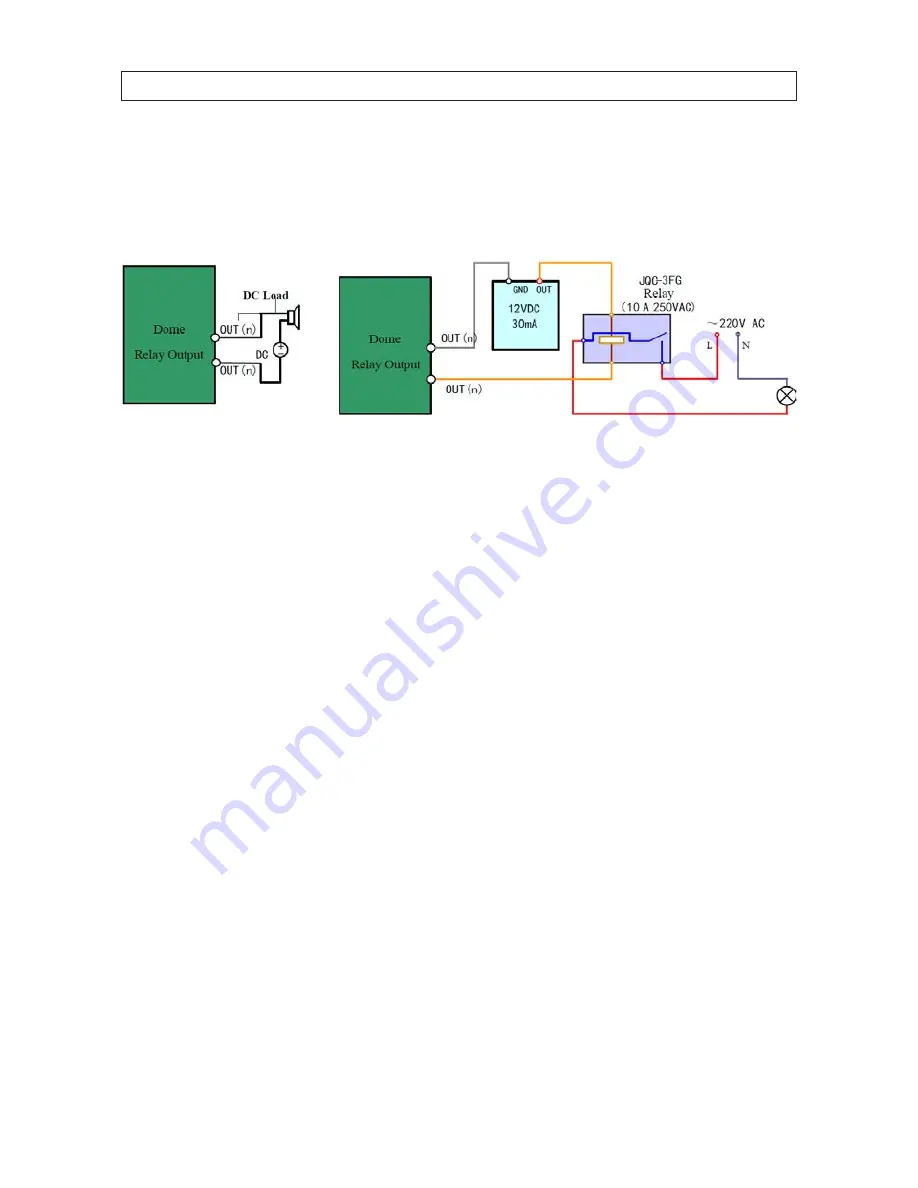
The camera can be connected with 2 alarm inputs (0~12 Vdc) and 1 alarm output. Refer to the following diagrams for the alarm
output connections:
Alarm out connections
The alarm provides the relay output (no voltage), and the external power supply is required when it connects to the alarm device.
With a DC power supply (left diagram), the input voltage must be no more than 12 Vdc, 30 mA. For AC power supply (right
diagram), the external relay must be used to prevent damages to the camera and avoid risk of electric shock.
2.1.3 Set the DIP switches
DIP switches, located in the housing are used to setup the RS-485 network address (switches 1 - 5), baud rate (switches 6 - 7), and
protocol (switches 8 - 9). These switches can also be setup manually or through the DVR PTZ interface.
DIP switch 10 provides RS-485 end-of-line termination and cannot be set using the DVR interface. If used, it must be set by opening
the camera enclosure and manually setting the switch to ON.
Using the tables below, set the switches in accordance with the following:
•
The default camera address is 0, the default baud rate is 2400, and the default status of the RS-485 network 120 Ω end-of-line
terminator is OFF.
•
The address of the devices (cameras) RS-485 network must each be different.
•
The baud rate must be the same for each device on the RS-485 network.
•
The DIP switches 1 - 9, used for setting the address, baud rate, and protocol of the RS-485 network, function logically in this
way: ON=1 and OFF=0.
•
The camera is self-adaptive to the Pelco-P, Pelco-D and Private-Code protocols. You don’t have to set the DIP switches for these
RS-485 control protocol.
To set the DIP switches manually, do the following:
1.
Remove the lower dome cover from the camera by extracting the three screws.


