background image

5

High Performance IR CCTV Bullet Camera User Manual

SECTION 2: INSTALLATION

3. 

Drill a 3/4” hole for the drop cable, if necessary.

4. 

Anchor the mounting plate to the mounting surface using the screws provided, or screws better suited for the surface 
structure. 

5. 

Route the drop cable through the hole through the base plate, or through the cable guide in the mounting bracket, then 
attach the camera to the mounting plate using the four (4) machine screws provided. 

6. 

Connect the camera drop cable to video and power cables as required. 


NOTE

Drop cable connectors are not waterproof. 

2.3  Camera adjustments

In this procedure, set the camera to point at your surveillance target. Rotate the far - near and tele - wide rings to frame the video 
image. 

1. 

Apply power to the camera.

2. 

Observe video from your camera on a monitor. 

a. 

If using a hand-held CCTV video setup monitor with your camera: 

i. 

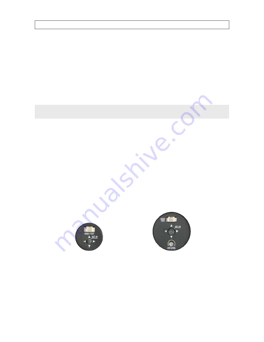
Remove the cover to the OSD control panel by unscrewing it counter clockwise. 

BLK-CPB700R65 OSD Controls

BLK-CPB700R150 and BLK-CPB700R300 OSD Controls

ii. 

Connect the BNC adapter cable to the VIDEO TEST port on the OSD control panel.

iii.  Connect a CCTV setup monitor to the BNC adapter cable. 

b. 

If using a CCTV video system monitor to setup your camera, connect the video output of the camera to your CCTV 
monitor. 

Содержание BLK-CPB700R150

Страница 1: ...ra User Manual Products BLK CPB700R65 BLK CPB700R150 BLK CPB700R300 Please read this manual before using your camera and always follow the instructions for safety and proper use Save this manual for f...

Страница 2: ...ICE Observint Technologies Observint products are designed to meet safety and performance standards with the use of specific Observint authorized accessories Observint disclaims liability associated w...

Страница 3: ...Mounting the camera 4 2 3 Camera adjustments 5 SECTION 3 Software Setup 8 3 1 LENS 8 3 2 EXPOSURE 9 3 3 WHITE BAL 12 3 4 DAY NIGHT 13 3 5 3DNR 15 3 6 SPECIAL 16 3 7 Adjust 22 3 8 RESET 23 3 9 EXIT 23...

Страница 4: ...ity is high Very high humidity levels can reduce image quality Do not install the camera under unstable lighting conditions Severe lighting change or flicker can cause the camera to work improperly Do...

Страница 5: ...or 700 TV lines 3DNR 2D or 3D for no noise or ghosting effect Maximum sens up x2 x256 OSD control functions DC auto iris varifocal lens 32 digital zoom Backlight compensation BLC and Day Night mode Mo...

Страница 6: ...our 4 coarse threaded screws to secure the base plate to the mounting surface Four 4 machined screws to secure the camera bracket to the base plate Mounting plate Hex wrench for adjusting the camera b...

Страница 7: ...User Manual SECTION 1 INTRODUCTION 1 1 2 Tools you need To install the camera you will need 12 Vdc or 24 Vac power source Tools for mounting the camera Video and power extension cables if needed Hand...

Страница 8: ...transmission of the video signal across coax 75 cable Power Connector Power Polarity Indicators Video BNC Connector 2 2 Mounting the camera The camera can be mounted on any surface with sufficient st...

Страница 9: ...cableconnectorsarenotwaterproof 2 3 Camera adjustments In this procedure set the camera to point at your surveillance target Rotate the far near and tele wide rings to frame the video image 1 Apply po...

Страница 10: ...ntrol 360 180 360 6 Rotate the Far Near adjustment ring and the Tele Wide adjustment ring to improve the image of the your surveillance target 7 Configure your camera using the software menus in the O...

Страница 11: ...camera operating in a dark environment unscrew the OSD panel access cover to access the OSD controls 2 While observing the video image from the camera use a screwdriver to turn the LED LEVEL screw to...

Страница 12: ...on the OSD control panel to navigate through the menu system Press the joy stick in toward the camera to enter the SETUP menu or select an entry rock the stick up or down to highlight an item in the l...

Страница 13: ...R This function is used to select automatic AUTO shutter speed control or set the shutter speed manually SHUTTER speed can between 1 60 sec and 1 100 000 sec AGC AUTOMATIC GAIN CONTROL Higher gain inc...

Страница 14: ...n to save changes and return to the EXPOSURE menu BLC Back Light Compensation This feature enables the camera to compensate for strong back light conditions in a selected area of the image OFF The BLC...

Страница 15: ...tick in twice to return to the BLC menu DEFAULT Select DEFAULT to revert to the default AREA position and size RETURN Select RETURN to return to the EXPOSURE submenu HSBLC Highlight Suppression Back L...

Страница 16: ...Select RET to return to the EXPOSURE menu OUTDOOR The D WDR is preset with default LOW LEVEL and HIGH LEVEL settings for normal outdoor lighting condition These settings can be adjusted in the OUTDOO...

Страница 17: ...this option Set the white balance using ATW or AWC Select MANUAL Rock the joystick right and or left to Increase or decrease the value of BLUE B gain or RED R gain while monitoring the color of the im...

Страница 18: ...ce IR SMART is applied to objects in a specified area of the image IRSMARToff IRSMARTon Selecting IR SMART ON opens the IR SMART sub menu where you can set the IR gain and position and size of the tar...

Страница 19: ...se the SETUP menu COLOR The picture is displayed in color AUTO In this mode the camera automatically switches to COLOR in normal condition and to B W mode when ambient illumination is low Selecting th...

Страница 20: ...reduction The default setting is 200 maximum RETURN Select RET to return to the SETUP menu or END to close the SETUP menu 3 6 SPECIAL Selecting SPECIAL opens a feature list of special camera function...

Страница 21: ...sor to the position in the character array before the 0 top line leftmost position and press the joystick in to select it blank character To clear all entries in the title highlight CLR then press the...

Страница 22: ...e D ZOOM feature Move the cursor to point at D ZOOM then rock the joystick right to set the RANGE magnification Similarly adjust the PAN and TILT options to move to the portion of the image you want t...

Страница 23: ...nk in the background AREA DISPLAY Move the cursor to AREA DISPLAY then rock the joystick right or left to select ON to configure that area or OFF to disable that area If ON push the joystick in to ope...

Страница 24: ...over image are color coded and can be reshaped To setup a privacy for the area selected Set the cursor on AREA DISPLAY and rock the cursor to ON to use the area or OFF to disable it If set to ON press...

Страница 25: ...to complete the operation RETURN Select RETURN to return to the SPECIAL menu DEFOG The DEFOG function improves object recognition in foggy or dusty weather condition DEFOGoff DEFOGon OFF Select OFF to...

Страница 26: ...mage from your camera SHARPNESS With the cursor pointing at SHARPNESS rock the joystick right or left as necessary to produce the clearest image from your camera MONITOR Rock the joystick right or lef...

Страница 27: ...SETUP 3 8 RESET Use RESET to revert the camera configuration settings to the factory default values FACTORY Select FACTORY to reset the camera configuration RETURN Rock the joystick to select RETURN...

Страница 28: ...a soft cloth moistened with a mild detergent solution then rinse and dry it with a soft cloth Remove all foreign particles such as plastic or rubber materials attached to the camera housing These may...

Страница 29: ...h Sens UP OFF AUTO X2 X256 Backlight compensation OFF BLC HLC D WDR OFF INDOOR OUTDOOR Motion detection 4 zones Privacy masking 8 zones DIS Digital Image Stabilizer OFF ON Communication Coaxial I F UT...

Страница 30: ...F 140 F 20 C 60 C humidity 20 RH 95 RH Operating temperature humidity 14 F 122 F 10 C 50 C humidity 20 RH 80 RH Dimension w h d 2 87 in 3 19 in 8 03 in 73 mm 81 mm 204 mm 3 31 in 3 50 in 8 98 in 84 m...

Страница 31: ...or If you have an intermediate device set the impedance 75 Hi Z properly and check the cable connections The camera is not working properly and the surface of the camera is hot Verify that the camera...

Страница 32: ...28 APPENDIX B CAMERA DIMENSIONS APPENDIX B Camera Dimensions BLK CPB700R65 Front 3 19 2 87 8 03 180 360 360 Side...

Страница 33: ...29 High Performance IR CCTV Bullet Camera User Manual APPENDIX B CAMERA DIMENSIONS BLK CPB700R150 8 98 Side 3 31 3 50 Front 360 360 180...

Страница 34: ...30 APPENDIX B CAMERA DIMENSIONS BLK CPB700R300 360 180 360 11 42 2 68 6 30 7 41 3 94 5 28 3 82 3 46 Front Side...

Отзывы: