11
CHAPTER 3: Installation
Installing the Terminal Eliminator Plus (TEP) involves between four and
eight steps, depending on your application:
1. Setting the internal DIP switches.
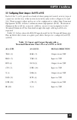
2. Configuring the DTE/DCE shunt jumpers.
3. Tying signal ground to frame ground with jumper W1 (optional).
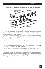
4. Inserting the RAM upgrade chip (optional).
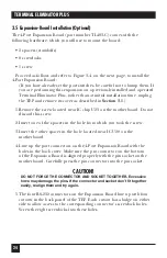
5. Installing the 4-Port Expansion Board (optional).
6. Rackmounting the TEP (optional).
7. Connecting your devices to the slave ports and master port.
8. Connecting the TEP to electric power.
3.1 Setting the Internal DIP Switches
There are six screws screwed into the enclosure on either side of the TEP:
three above a horizontal seam, three below. For each side, unscrew and retain
the three screws above the seam. This will allow you to remove the cover of
the unit’s enclosure and expose the motherboard.
Figures 3-1 and 3-2 on the next two pages show the location of the TEP’s
internal DIP switches for the standard 5-port unit and for the 4-Port
Expansion Board. There are two types of internal DIP switches: option
switches for individual ports (SWA-SWE and SWH-SWK) and system-option
switches that affect all ports (SWF and SWG). The possible switch settings are
discussed in
Sections 3.1.1
and
3.1.2
.
3.1.1 I
NDIVIDUAL
P
ORT
S
WITCHES
Each port can be configured individually for the following options:
Baud Rate: 110, 300, 600, 1200, 2400, 4800, 9600, or 19,200 bps
Parity: Even, odd, or none
Data Bits per Word: 7 or 8
Flow Control: Hardware (DTR/CTS) or software (X-ON/X-OFF); also
(master port only) X-ON/poll
Buffer Control (slave ports only): Always buffer data or only buffer in
Conversation modes
Trigger Reinitialization and Load Defaults (master port only)
3. Installation


