background image

20

TERMINAL ELIMINATOR PLUS

3.1.2.K  Other Nonprintable-Character Stripping (SWG Position 3)

To assure that your master device isn’t adversely affected by unexpected
control codes, you might want the TEP to strip nonprintable characters (not
including carriage returns and line feeds) out of the data records it receives
from slaves before it retransmits them: Set position 3 of SWG to OFF. If you
want the TEP to leave the nonprintable characters in, set position 3 ON.

3.1.2.L  Carriage-Return Insert After End of Record (SWG Position 4)

If you want the Terminal Eliminator Plus to insert a carriage return at the end
of each valid slave record that doesn’t already end with a carriage return, set
position 4 of SWG to OFF. If you don’t want the TEP to insert any carriage
returns, set position 4 ON.

3.1.2.M  Transmission Delay After Carriage Returns (SWG Position 5)

If your master device is an older hardcopy-display unit that needs a delay after
each carriage return to move its print head, you will want to set position 5 of
SWG to ON, which will cause the TEP to wait for 100 ms (one-tenth of a
second) after transmitting a carriage return to the master before transmitting
more data. If you have no need for this delay, set position 5 OFF.

3.1.2.N  Line-Feed Insert After Carriage Returns (SWG Position 6)

If you want the Terminal Eliminator Plus to insert a line feed after every
carriage return it transmits to the master, set position 6 of SWG to OFF. If you
don’t want the TEP to insert line feeds, set position 6 OFF.

3.1.2.O  Slave-Data Transmission (SWG Position 7)

If you want the TEP to switch from one slave’s data stream to the next on a
record-by-record basis, set position 7 of SWG to ON. If you don’t want the
TEP to switch to another slave until the “no receive” timeout occurs (usually
after several records are transmitted from the current slave), set position 7
OFF. See 

Section 5.5.4.O

.

Содержание Terminal Eliminator Plus

Страница 1: ...upport 24 hours a day 7 days a week Call 724 746 5500 or fax 724 746 0746 Mail order Black Box Corporation 1000 Park Drive Lawrence PA 15055 1018 Web site www blackbox com E mail info blackbox com MARCH 2001 TL482A R3 TL482AE R3 TL483 C TL484 TL486 Terminal Eliminator Plus 0 1 2 3 4 5 6 7 8 PWR STATUS TERMINAL ELIMINATOR PLUS ...

Страница 2: ...terference in which case the user at his own expense will be required to take whatever measures may be necessary to correct the interference Changes or modifications not expressly approved by the party responsible for compliance could void the user s authority to operate the equipment This digital apparatus does not exceed the Class A limits for radio noise emission from digital apparatus set out ...

Страница 3: ... aparato eléctrico debe ser montado a la pared o al techo sólo como sea recomendado por el fabricante 8 Servicio El usuario no debe intentar dar servicio al equipo eléctrico más allá a lo descrito en las instrucciones de operación Todo otro servicio deberá ser referido a personal de servicio calificado 9 El aparato eléctrico debe ser situado de tal manera que su posición no interfiera su uso La co...

Страница 4: ...r una antena externa deberá ser localizada lejos de las lineas de energia 16 El cable de corriente deberá ser desconectado del cuando el equipo no sea usado por un largo periodo de tiempo 17 Cuidado debe ser tomado de tal manera que objectos liquidos no sean derramados sobre la cubierta u orificios de ventilación 18 Servicio por personal calificado deberá ser provisto cuando A El cable de poder o ...

Страница 5: ...xpansion Chip Optional 22 3 5 Expansion Board Installation Optional 24 3 6 Rackmounting the TEP Optional 26 3 7 Connecting Devices to the Master and Slave Ports 28 4 Configuration 29 4 1 The Initialization Menu 29 4 2 Menu Options 31 5 Operation 34 5 1 The Master Device 34 5 2 Valid Command Strings 36 5 3 The Data Direction Modes in Detail 38 5 4 Buffer Allocation 44 5 5 Data Processing 45 5 6 Mas...

Страница 6: ...ont mounted LEDs 1 Power 9 Port Activity Connectors Standard 5 port unit TL482A E R3 5 DB25 female Standard unit plus 4 Port Expansion Board TL483 C 9 DB25 female Pins Supported 1 2 3 4 5 6 7 8 20 and 22 Power For 120 VAC 60 Hz operation From wallmount power supply Optimal input 115 VAC 60 Hz 175 mA Output 18 VAC CT 2 2 A For 240 VAC 50 Hz operation From wallmount power supply Optimal input 230 VA...

Страница 7: ... primary types of applications are typical A Using the TEP to concentrate the console output of many mainframe computers in a large computer center to one operator s console The operator will then receive all messages to mount magtapes etc at one convenient location B Using the TEP to poll or concentrate the output from other devices such as bar code readers scales security systems etc to a master...

Страница 8: ...ll slave ports When interactive operation is required you can access Conversation Mode slave master to allow the master device or user to communicate bidirectionally with one selected slave device The master port s non command data is transmitted to the single slave the master selects This slave s data is transmitted to the master in the format you established at installation and initialization ti...

Страница 9: ...Ds 5 through 8 will always be dark 2 3 The Internal DIP Switches and Reset Button All of the hardware controls for your Terminal Eliminator Plus are internal Of most importance are the DIP switches two system switches SWF and SWG which determine data formatting and allow you to tailor the unit s major functions to the needs of your application and five or nine port switches SWA through SWE plus SW...

Страница 10: ...l allow you to remove the cover of the unit s enclosure and expose the motherboard Figures 3 1 and 3 2 on the next two pages show the location of the TEP s internal DIP switches for the standard 5 port unit and for the 4 Port Expansion Board There are two types of internal DIP switches option switches for individual ports SWA SWE and SWH SWK and system option switches that affect all ports SWF and...

Страница 11: ...e port 3 SWE for slave port 4 BACK PORT 4 PORT 3 PORT 2 PORT 1 PORT 0 DTE DCE J7 U23 U20 J1 W1 VR1 RESET BUTTON S1 R1 SW G SW F SW E SW D SW C SW B SW A SYSTEM SWITCHES SWF SWG INDIVIDUAL PORT SWITCHES STATUS INDICATORS FRONT DTE DCE DTE DCE DTE DCE DTE DCE OFF OFF OFF OFF OFF OFF OFF PORT 4 PORT 3 PORT 2 PORT 1 PORT 0 PORT LEDS PWR LED LOCKOUT RESET BUTTON Fig 3 1 The Terminal Eliminator Plus s m...

Страница 12: ...2 on page 10 lists the possible settings for each slave port s switch You can set the expansion board switches before you actually insert the board into the TEP just be careful not to bump the switches when you insert the board text continues on page 16 BACK FRONT INDIVIDUAL PORT SWITCHES PORTS 5 THRU 8 PORT 8 PORT 7 PORT 6 PORT 5 SWK OFF SWJ OFF SWI OFF SWH OFF PORT 5 DTE DCE PORT 6 DTE DCE PORT ...

Страница 13: ...en both switches are set to ON the TEP will generate a self test message When positions 7 and 8 are set to ON the TEP resets itself and reloads its NVRAM with the factory default values for all items on its initialization menu This will come in handy if a menu option is set wrong in such a way that it prevents you from activating the menu to fix it Set one or both of these positions OFF and reset ...

Страница 14: ...s 110 ON ON ON 300 OFF ON ON 600 ON OFF ON 1200 OFF OFF ON 2400 ON ON OFF 4800 OFF ON OFF 9600 ON OFF OFF 19 200 OFF OFF OFF PARITY None ON ON Even OFF ON Odd ON OFF None OFF OFF DATA BITS Eight ON Seven OFF FLOW CONTROL DTR CTS ON X ON X OFF OFF BUFFER CONTROL Buffer data in Conversation modes only ON Always buffer OFF See Section 5 5 3 ...

Страница 15: ...N 1 2 3 4 5 6 7 8 STATUS MESSAGES Disabled ON Enabled OFF STANDARD MODE Concentrate and Broadcast ON Concentrate Only OFF BROADCAST MODE FLOW CONTROL Acknowledged ON Ignored OFF ECHO MASTER INPUT Enabled ON Disabled OFF CARRIAGE RETURN BEFORE DATA FROM DIFF SLAVE Enabled ON Disabled OFF LINE LABELING STYLE Label all lines from same slave ON Label first lines only OFF LABEL ISOLATION Place label on...

Страница 16: ...d ON Enabled OFF TRANSMISSION DELAY AFTER CARRIAGE RETURNS Enabled 100 ms delay ON Disabled no delay OFF LINE FEED INSERT AFTER CARRIAGE RETURNS Disabled ON Enabled OFF SLAVE DATA TRANSMISSION Transmit one record from current slave one from next slave etc ON Transmit records from current slave until timeout occurs then switch OFF POSITION 8 RESERVED FOR FUTURE USE Table 3 4 The System DIP Switch S...

Страница 17: ...t Mode Flow Control SWF Position 3 When the Terminal Eliminator Plus receives data from the master to be broadcast to all slaves and one or more of the slaves have flow controlled the TEP OFF you have two options You can choose for the TEP to buffer the broadcast data then transmit it all at once when all the slaves are ready to receive it by setting position 3 of SWF to ON Alternatively you can c...

Страница 18: ...elves set position 7 ON 3 1 2 H Slave Data That Precedes Beginning Record Char SWF Position 8 You can assign a character that the Terminal Eliminator Plus will recognize as the beginning record character the character that marks where a slave s data record begins see Sections 4 2 1 and 5 5 3 If you want the TEP to discard any slave data that precedes the beginning record character set position 8 o...

Страница 19: ...ns SWG Position 5 If your master device is an older hardcopy display unit that needs a delay after each carriage return to move its print head you will want to set position 5 of SWG to ON which will cause the TEP to wait for 100 ms one tenth of a second after transmitting a carriage return to the master before transmitting more data If you have no need for this delay set position 5 OFF 3 1 2 N Lin...

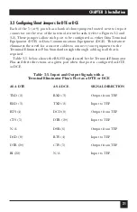
Страница 20: ...to connect your equipment to the Terminal Eliminator Plus Standard straight through cabling is all that is required Table 3 5 below shows the RS 232 signals used by the Terminal Eliminator Plus and their directions at a given port when that port is configured as DTE or DCE Table 3 5 Input and Output Signals with a Terminal Eliminator Plus s Port as a DTE or DCE AS A DTE AS A DCE SIGNAL DIRECTION T...

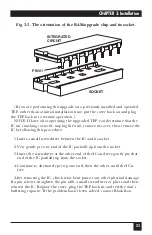
Страница 21: ...procedure If you are performing this upgrade on a previously installed and operated Terminal Eliminator Plus rather than at initial installation time unplug the TEP and remove its cover as described in Section 3 1 First locate the empty chip socket labeled U6 on the motherboard This socket is not shown in Figure 3 1 but it is directly behind the front panel LEDs Position the IC so that its notch i...

Страница 22: ...ery gently pry one end of the IC partially up from the socket 3 Insert the screwdriver at the other end of the IC and very gently pry that end of the IC partially up from the socket 4 Continue to alternately pry up one end then the other until the IC is free After removing the IC check it for bent pins or any other physical damage If a pin is bent straighten the pin with a small screwdriver or pli...

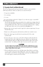
Страница 23: ...o not discard this screw 2 Insert one of the spacers in the hole from which you took the screw 3 Insert the other spacer in the hole located near IC U20 on the motherboard 4 Line up the port connectors on the 4 Port Expansion Board with the holes in the back cover Make sure the pin connector on the bottom of the Expansion Board is aligned properly with the pin socket on the motherboard Carefully p...

Страница 24: ... through the other spacer hole into the other spacer The 4 Port Expansion Board is now installed If you haven t set the Expansion Board s switches yet see Section 3 1 If you are performing this upgrade on a previously installed and operated TEP rather than at initial installation time put the cover back on and plug the TEP back in to resume operation Fig 3 4 Installing the 4 Port Expansion Board ...

Страница 25: ... the desired settings as described in Sections 3 1 through 3 3 If this is part of your initial TEP installation rather than a later alteration make sure that the internal power supply connector is properly attached to the 4 pin male connector on the motherboard then replace the unit s cover 1 Remove but don t discard the front four screws from each side of the Terminal Eliminator 2 Position the ra...

Страница 26: ... the mounting holes on the rack see Figure 3 6 5 Align the grooves in the TEP s rackmount brackets with the clips you just attached to the rack 6 Screw four mounting screws not supplied through the grooves in the brackets and into the clips on the rack As before make sure these screws are tight The Terminal Eliminator Plus is now installed in your equipment rack Fig 3 6 Mounting the TEP in a rack ...

Страница 27: ...sole 1 If you haven t rackmounted the TEP and so already taken these steps verify that the power supply connector is properly inserted into the 4 pin male connector on the Terminal Eliminator Plus s motherboard then replace the unit s cover 2 Connect the input device cables to slave ports 1 through 4 or 1 through 8 3 Connect the master console cable to the master port port 0 Lastly plug the wallmo...

Страница 28: ...e code and Escape code are used to edit input and abort exit functions see below You can bring up the initialization menu on the master device s screen from either of the Concentrate modes by entering from the master device the four characters INIT followed by a carriage return INITIALIZATION MENU 1 See Set beginning record character 2 See Set ending record character 3 See Set labels inserted at b...

Страница 29: ...ing you will receive detailed instructions on the valid range of data that can be entered For example if you select option 6 to see and set the maximum output line length then after you give it a particular port number you will be prompted Enter the maximum size of any output line 1 255 or 0 infinite 72_ The 72 from the line above is the current default setting If you hit ESCAPE or ENTER it will r...

Страница 30: ...tion to have a character value the range is 0 to 255 decimal 00 to FF hex or 256 disabled then when the TEP is receiving a slave s record and senses the character you select it will treat the record as having ended at that point The factory default for this selectable by port option is 13 decimal 0D hex the ASCII carriage return If you disable this character for a given port do not also disable bo...

Страница 31: ...able by port option is disabled Here time is measured in ticks of the TEP s internal clock each tick is equivalent to 10 4167 milliseconds The maximum delay is 65535 ticks equivalent to 11 minutes and 22 66 seconds Table 4 1 below shows equivalences for some rounder more useful figures Table 4 1 Equivalences for Setting the No Receive Timeout TIME INTERVAL NUMBER OF TICKS 250 ms 24 500 ms 48 750 m...

Страница 32: ...l same for all ports option is N 4 2 8 THE BACK TO CONCENTRATE MODE TIMEOUT If you allow this option to have a value other than zero the range is 1 to 65535 times 50 ms or 0 disabled the TEP will automatically exit either Conversation mode and return to its standard Concentrate mode when this amount of time elapses without receipt of data from the master device Refer to Section 5 3 2 The factory d...

Страница 33: ...your data If the data contains no non printable cursor positioning control codes other than carriage returns and line feeds you can get a readable display by using a dumb terminal or a dumb printer mode If your data contains cursor positioning codes however you have two choices You can use a dumb master and set the TEP to strip the codes out refer to Section 5 5 4 M if this produces readable resul...

Страница 34: ...ly Mode DISCONNECT The TEP has switched back to the standard Concentrate mode KEYBOARD INPUT TIMED OUT Master input echoing is enabled see Section 3 1 2 D the TEP is not in a Conversation mode and the 3 second no data to echo timeout has occurred This message followed by its two carriage returns allows the TEP to resume sending slave data on a new line after the user stops typing in data to echo W...

Страница 35: ...consecutive command characters from the master device The command character can be one of four different characters N O P or Q selected from the initialization menu that is sent to the master device when the Initialization command is entered see below Thus a valid Abort command string would be NNNNNNNN OOOOOOOO PPPPPPPP or QQQQQQQQ When cascading multiple TEPs each layer of units should be assigne...

Страница 36: ...rs BBBB followed by a carriage return character ASCII CR If the current mode is one of the Concentrate modes include an ASCII port number after the four B s to indicate which slave device should receive the break sequence for example BBBB1 CR to send a break to the slave device on port 1 5 2 9 CHAINED COMMANDS It is possible to go from either a a Conversation mode with one slave device to a Conver...

Страница 37: ...hen a user a first plugs in the unit b resets the unit or c exits Broadcast Only Mode or either Conversation mode by issuing the Disconnect or Abort command string see Sections 5 2 1 and 5 2 2 from the master device To get to Concentrate and Broadcast Mode position 2 of system switch SWF must be ON If it is the TEP will go to this mode when a user a first plugs in the unit b resets the unit or c e...

Страница 38: ...ve that is in a Conversation mode with the console or if you want to switch to Broadcast Only Mode you can either return to Normal Mode and enter the appropriate one of the Cn CR Tn CR or BC CR commands as described in Sections 5 2 4 through 5 2 5 or you can enter a chained command as described in Section 5 2 9 The only difference between regular Conversation Mode and Transparent Conversation Mode...

Страница 39: ...ep process described in the previous section But activating a conversation with a device on one of the subsidiary units requires additional steps First make sure that the disconnect abort command character for each layer of TEPs is different see Section 4 2 7 Then change the mode of each TEP between the master device and the selected slave device one at a time starting at the first layer TEP the o...

Страница 40: ...nter Broadcast Only Mode You can enter Broadcast Only Mode with a single command from a Concentrate mode see Section 5 2 5 or a chained command from a Conversation Mode see Section 5 2 9 The Disconnect and Abort commands see Sections 5 2 1 and 5 2 2 are the only commands the TEP will execute in the Broadcast Only Mode Return to your TEP s standard Concentrate mode to enter any other command 5 3 5 ...

Страница 41: ... the command character of the third layer units must have changed to something other than those used by either of the higher two layers For example assuming the first layer command character is N the second layer character is O and the third layer character is P you want to exit the conversation immediately throwing away any master port data that might remain in the TEP s buffers and you want to e...

Страница 42: ...FF the Terminal Eliminator Plus will bypass any port that is exercising flow control When the TEP encounters a port that is configured for hardware or software flow control and has dropped DTR CTS or sent an X OFF character it will not transmit that byte to the port Instead the TEP continues transmitting to the other ports in consecutive order When the buffered port raises DTR or sends an X ON cha...

Страница 43: ... of RAM reserved exclusively for that port In this way a single port cannot monopolize all the Terminal Eliminator s buffer space The remaining memory is distributed among all active ports according to the current demand If each port were given an equal amount of the total buffer space and some of the ports were inactive there would be a great deal of wasted buffer not available for use Dynamic al...

Страница 44: ...n 4 on This may be required by old hardcopy terminals 5 5 2 SCANNING FOR SLAVE RECORDS Records from different slaves are transmitted in round robin fashion That is each port is checked in ascending order from Port 1 through Port 4 or 8 You can select when the TEP will switch from the current port to the next sequential port by setting position 7 of system switch SWG Refer to Section 5 5 4 O 5 5 3 ...

Страница 45: ...uffered enough data from that slave device to define at least one valid record Valid record requirements are defined by the user at initialization time 3 The master port is not flow controlled OFF DTR input low for example Valid records can be defined as any combination of the following 1 Received data 1 or more bytes terminated by a user selected end of record character for example ETX code carri...

Страница 46: ...s must be 80 bytes long for slave port 4 that records must be 132 characters or terminated by an inter record gap of 250 ms and so on 5 5 4 FORMATTING OF SLAVE DATA IN CONCENTRATE MODES AND CONVERSATION MODE The slave data that is sent to the master device can optionally be formatted to match your display needs in either of the Concentrate modes or Conversation Mode not Transparent Conversation mo...

Страница 47: ... be any printable ASCII string up to 16 characters long it can also be a NULL string equivalent to no label at all This label is inserted at the beginning of data as well as when data is interrupted by a line wrap caused by the record reaching the maximum line length substantial labels Slave 1 xyz null labels xyz Slave 2 xyz xyz NOTE The example above assumes a carriage return follows the data to ...

Страница 48: ...sumes a carriage return follows the data to perform a line wrap 5 5 4 E Transmit or Don t Transmit Slave Data That Precedes User Selected Beginning of Record Character System switch SWF position 8 ON to pass data before the beginning of record character user selected beginning of record character FS ASCII field separator control code user selected end of record character ETX ASCII end of text cont...

Страница 49: ...ypically data sent to a display device would contain a CR or CR LF pair before or at the maximum line length If you sent 132 bytes of data followed by a CR LF pair to a printer that has only 80 characters per line then usually the 81st to 132nd characters of the data will not be printed or they will wrap to the next line causing lines to be lost at the bottom of the page Because the Terminal Elimi...

Страница 50: ... your particular display device These can include codes that cause the device to 1 clear the screen 2 switch to reverse video 3 position the cursor at a certain row and column 4 ring its internal bell Because different slave devices may have been designed to interface with different types of display device than the one you re using you may experience weird problems when receiving these nonprintabl...

Страница 51: ...received until it finds an inter record gap inter record gaps that occurred between existing buffered records are remembered and treated as such that meets or exceeds the user assigned time limit for this particular slave port After this timeout it will search through its internal receive buffers for data from the other slave ports in sequential order looking for a complete record to transmit When...

Страница 52: ...e device attached to the master port typically a PC running a communication program controlled by a user sends it an ASCII code defined as the X ON character After receiving an X ON when the TEP has a complete record for any port it will send this single record but it will not send any more until it receives another X ON character in other words it will X OFF itself If the TEP does not have a comp...

Страница 53: ...ion including The nature and duration of the problem When the problem occurs The components involved in the problem Any particular application that when used appears to create the problem or make it worse 6 2 Shipping and Packaging If you need to transport or ship your Terminal Eliminator Plus Package it carefully We recommend that you use the original container Before you ship a unit for repair o...

Страница 54: ...1000 Park Drive Lawrence PA 15055 1018 724 746 5500 Fax 724 746 0746 Copyright 2001 Black Box Corporation All rights reserved ...

Отзывы: