


•
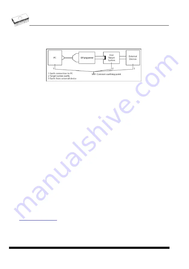
For laptop or other PC that is not connected to common earth point: make hard - wired
connection from laptop to common earth point (for example use LPT or COM port D –
connector).
•
Any devices connected to target system must be connected to common earth point too.
Direction of connect B+K PRECISION ISP programmer to target
system:
During in-system programming you connect two electrical devices – ISP programmer and
target system. Unqualified connection can damage these devices.
Note: When you don’t keep below directions and you damage programmer during in-system
programming, it is damage of programmer by unqualified manipulation and is out of warranty.
1. Turn off both devices – ISP programmer and target device.
2. Assign same GND potential for all devices, e.g. connect GND of all devices by wire.
3. Insert one connector of ISP cable to ISP programmer, turn on programmer and control
program.
4. In control program select target device and operation options.
5. Start action on target device (read, program).
6. After direction of control program, connect other ISP cable connector to target system and
turn on it.
7. After direction of control program, disconnect other ISP cable connector from target system
and turn off it.
8. If you need another action on target device, you continue with step 5.
The recommendation for design of target system with ISP
programmed device
The target system must be designed to allow all signals, which are use for In-system
programming to be directly connected to ISP programmer via ISP connector. If target system
use these signals for other function, is necessary isolated these signals. Target system
mustn’t affect these signals during In-system programming.
For in-system programmable devices manufacturers publish application notes. Design of B+K
PRECISION programmers together with respect of these application notes allow proper In-
system programming. Condition is exactly respect these application notes. Applications
notes, which B+K PRECISION use in ISP programmers, are published in
Please, read some notes for following recommended circuits.
•
Purpose of D1 diode is to protect the target circuit against a higher voltage, which is
provided by ISP programmer.
130
Содержание 844USB
Страница 7: ...Introduction 7 ...
Страница 12: ...Quick Start 12 ...
Страница 14: ...4 check if the device is blank click on 5 program device click on 6 additional verify of device click on 14 ...
Страница 15: ...Detailed description 15 ...
Страница 16: ...859 16 ...
Страница 28: ...866B 28 ...
Страница 41: ...844USB 41 ...
Страница 50: ...848A 50 ...
Страница 56: ...Setup 56 ...
Страница 60: ...Step 6 Check your setting and then click on Install button Step 7 Installation process will start 60 ...
Страница 65: ...Step 6 Click on Continue Anyway button For Windows Vista Click Install this driver software anyway 65 ...
Страница 67: ...Pg4uw 67 ...
Страница 116: ...About When you choose the Info command from the menu a window appears showing copyright and version information 116 ...
Страница 117: ...Pg4uwMC 117 ...
Страница 127: ...Common notes 127 ...
Страница 134: ...Troubleshooting and warranty 134 ...


