


Chapter 6
Statistics
Evia HF / HF-T Technical Manual
PAGE 77
6.4.2.2 Activity
This value reports any time that the sensor has detected patient activity. Presumably, most of this
activity presents normal activities of daily living. Values that may appear too high or too low for that
particular patient may represent inappropriate threshold settings for that patient.
6.4.2.3 Max Sensor Rate
This represents how much time the sensor-indicated rate is at the programmed maximum sensor rate.
Active patients may have relatively high percentages of time in this bin. For example, a runner who
runs an hour a day, reaching his or her max sensor rate, may expect to have a max sensor activity
value at 4%. Typically, many patients will have no or a very small percentage in this bin.
This data can assist in the analysis of heart and sensor activity. For example, a high value for the
activity may indicate that the sensor gain is set too high. In contrast, an extremely low value for activity
may indicate that the sensor gain is too low.
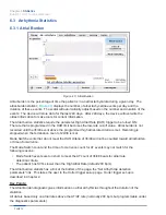
6.5 Pacing Statistics
6.5.1 Lead Impedance Trends with Lead Check
Evia CRT-Ps can perform lead impedance measurements for the atrial and right/left ventricular leads.
These measurements are stored in memory for use in lead impedance trend data as a function of time.
The pace current and voltage is measured in order to determine the lead impedance.
Every 30 seconds, the lead impedance measurements are taken and are available for diagnostic trend
display. The programmer will display a long-term trend of 240 days.
Impedance trends are always recorded. The lead impedance measurements are used to determine if a
lead failure has occurred. The range for normal lead impedance is from 100 to 2500 ohms.
If the Evia CRT-P detects a bipolar lead failure, polarity for the respective lead will automatically be
changed to unipolar configuration. A bipolar lead failure is verified if the lead impedance measurement
falls outside of the acceptable range for three consecutive readings. When a lead failure has been
detected, a message is displayed on the programmer screen at the next follow-up visit in order to notify
the physician of the change.
Lead Check is temporarily suspended during magnet application and is inactive during ERI.
Figure 46: Lead Impedance Trend
Содержание Evia HF
Страница 1: ...Cardiac Rhythm Management Heart Failure Therapy Evia HF HF T Evia HF HF T Technical Manual...
Страница 8: ...Chapter Table of Contents Evia HF HF T Technical Manual PAGE vi...
Страница 12: ...Chapter 2 Indications Evia HF HF T Technical Manual PAGE 4...
Страница 14: ...Chapter 3 Contraindications Evia HF HF T Technical Manual PAGE 6...
Страница 98: ...Chapter 7 Product Storage and Handling Evia HF HF T Technical Manual PAGE 90...
Страница 104: ...Chapter 9 Lead Connection Evia HF HF T Technical Manual PAGE 96...
Страница 118: ...Chapter 10 Elective Replacement Indication ERI Evia HF HF T Technical Manual PAGE 110...
Страница 130: ...Chapter 13 Order Information Evia HF HF T Technical Manual PAGE 122...
Страница 132: ...Chapter 14 Order Information Evia HF HF T Technical Manual PAGE 124...
Страница 136: ...PAGE 128 Appendix A Evia HF HF T Technical Manual...