Berthold castxpert LB 452 Скачать руководство пользователя страница 122

c

8 Troubleshooting

122

Rev. 04, 03/2015

b

8.2

Error Codes of the Evaluation Unit

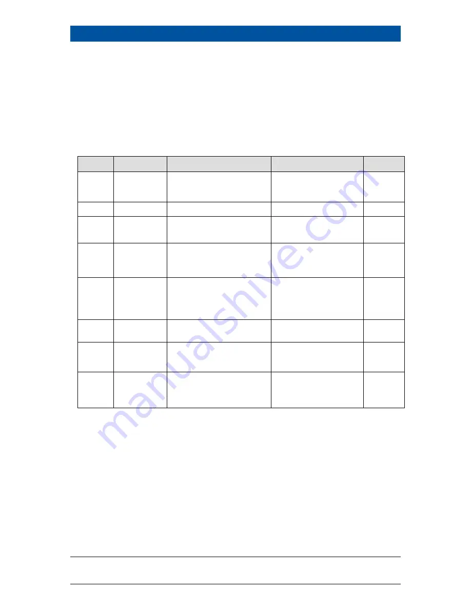
In the following tables you can find the EVU error codes which give you exact in-
formation on how to fix them. All castXpert LB 452 errors have the prefix "M", all
GAMMAcast LB67xx errors the prefix "D".

The detector error codes can be seen in the "48452BA1" manual in chapt. 7.1.

8.2.1

System

Code

Text

Description

Correction

Class

101

HW module
corrupted

Missing circuit board or incom-
patible test header

Carry out software up-
date

Contact service

Error

102

Device data

Data inconsistency found

Carry out factory reset

Error

103

RAM, Flash or
CPU

Error in main memory

Hardware error

Contact service

Error

104

WD reset

The system has been reset by
the watch dog (WD)

Hardware error

Contact service

Warning

105

WD failure

The watch dog (WD) was acti-
vated but the system was not
reset

Hardware error

Contact service

Error

106

WD off

The debug jumper is sticking,
the watchdog is disabled

Remove debug jumper

Error

107

RTC date/time

Error in the actual time clock or
invalid time

Check the date and
time settings

Contact service

Warning

108

Software ex-
ception

Software exception

Carry out software up-
date. If the error still re-
mains, contact the ser-
vice.

Error

Содержание castxpert LB 452

Страница 1: ...Evaluation unit LB 452 Operating Manual 47344BA2 Rev No 04 03 2015 Embedded Software as of vers 1 3 0 CU and 1 3 0 MU ...

Страница 2: ......

Страница 3: ...BERTHOLD TECHNOLOGIES GmbH Co KG Calmbacher Str 22 75323 Bad Wildbad Germany www Berthold com Telephone 49 7081 177 0 Fax 49 7081 177 100 industry Berthold com ...

Страница 4: ......

Страница 5: ...0 4 Start Up 23 4 1 Installation of the Evaluation Unit EVU 23 4 2 The Use of a Terminal Box 26 4 3 Configuring the Current Output 27 4 3 1 Configuring the Current Output on the Basic Module 28 4 3 2 Configuring the Current Output on Extension Module 31 4 4 Data Definition Profibus DP 32 4 5 Mounting an SD Card 33 5 Operation of the Software 35 5 1 Overview of the Standard Display 36 5 2 Operation...

Страница 6: ...ontrol 125 8 2 5 Process Connection 126 9 Maintenance 127 9 1 Installation of Modules 127 9 1 1 Installation of the Basic Module Extension Module 130 9 1 2 Installation of the Fieldbus Module 131 9 2 Replacing of Fuses 133 9 2 1 Replacing of Basic Module Fuse 134 9 2 2 Replacing of Extension Module Fuse 135 9 3 Cleaning 137 10 Decommissioning 139 10 1 Disposal of Measurement System 139 11 Technica...

Страница 7: ... Carry out maintenance Fix errors Disassemble Dispose of the device You must read through the entire manual We have tried to compile for you all information for safe and proper operation However should questions arise which are not answered in this manual please refer to BERTHOLD TECHNOLOGIES GmbH Co KG 1 2 Structure of the Manual This manual has been divided into chapters The order of the chapter...

Страница 8: ... and recognise possible dangers through their specialist training knowledge and expe rience as well as knowledge of the relevant regulations 1 6 Notation In this manual the following notations are used to state the software interface and the operation Identifier Meaning Example Quotation mark Field in the soft ware interface Calibrating Vertical line Path specification Settings Option Display Poin...

Страница 9: ... situation If the situation is not avoided death or serious bodily injury could result Possible consequences are described Measures for prevention are described Caution Possible consequences Mild or moderate injury Points out a possibly dangerous situation If the situation is not avoided minor or moderate bodily injury could occur Possible consequences are described Measures for prevention are des...

Страница 10: ......

Страница 11: ...ety instructions Carrying out the prescribed maintenance measures or having them carried out for you 2 2 Improper use D a n g e r Danger to life from electric shock The installation may only be carried out by a qualified electrician Electric shock Please adhere to the relevant safety regulations Only carry out maintenance work when the device is free of volt age Only open the device when free of v...

Страница 12: ...VU in a damaged or corroded condition Restructuring or changing the system components The device is not approved according to IEC 61508 Functional safety of safety related electric electronic programmable electronic systems If the product is used in a way which is not described in the present manual the device s protection is compromised and the warranty claim becomes invalid BERTHOLD TECHNOLOGIES...

Страница 13: ... person This can also refer to construction site personnel The persons in question must have experience in the transportation and assembly of heavy component parts Experts Experts are persons who have sufficient knowledge in the required area due to their specialist training and who are familiar with the relevant national health and safety regulations accident prevention regulations guidelines and...

Страница 14: ...c 2 Safety 14 Rev 04 03 2015 b ...

Страница 15: ...weisquelle konnte nicht gefun den werden You can connect the EVU to both radiometric detectors GAMMAcast and the elec tromagnetic measurement system ECcast When in doubt the instructions refer to the GAMMAcast instructions For specific information regarding ECcast refer to the ECcast supplemental instructions 3 2 Software The field device is delivered with pre installed software The revision statu...

Страница 16: ...he Main section control unit indicate the operation mode of the EVU The indicators 1 to 4 Fig 2 indicate the operation mode of each meas urement channel This shows which operation mode is active on each measurement channel If an error occurs at just one measurement channel Error LED lights up then the other measurement channels are not affected by this error The measurement of other channels conti...

Страница 17: ...est mode or if any other warning mes sage is present The current measurement is retained All possi ble error reports are described in chapt 8 Troubleshooting Run LED This LED Fig 2 Pos 3 lights up if the device is in operation and fault free The current measurement is carried out 3 4 3 Back View The following connections are located on the back of the EVU EVU power supply Power supply of channels ...

Страница 18: ...s for channel 1 2 Slots for channel 2 3 Slots for channel 3 4 Slots for channel 4 5 External power supply of the device in and power supply of the channels 1 4 out 6 Type plates 7 Serial ports unused 8 Ethernet and USB ports Fig 3 Back view of the EVU ...

Страница 19: ...n be individually measured at the same time Note Notes for the use of casting powder If casting powder is used for the casting process note that the height of the casting powder layer is partially measured via the mould level of the measurement device This means that the mould level appears to be somewhat higher than that corresponding to the actual mould level The magnitude of this deviation depe...

Страница 20: ...ade up of the following components LB 452 castXpert evaluation unit EVU Detector from the GAMMAcast series Radiation Source Mould Level Shielding 1 Fill level 2 Beam path 3 Measurement line for channel 1 4 Evaluation unit back view 5 Detector 6 Fluid metal in the mould 7 Radiation source in shielding Fig 4 Measurement Set up ...

Страница 21: ... of at least one basic module This is in dispensable for operating the EVU The following modules can also be installed in the EVU Extension Module Offers an extra current output a pulse input for digital inputs and 2 alarm relays Fieldbus Mod ule For transmitting measurement related data via an RS 485 port Profibus DP or an RJ 45 Ethernet port Profinet IO Further instructions on the extension modu...

Страница 22: ......

Страница 23: ...o the relevant safety regulations Only carry out maintenance work when the device is free of volt age Only open the device when free of voltage Attention Damage to the device or wrong measurement results Error in the calibration or in the setting of parameters Wrong measurement results Losses of production Damage in the system In general we would recommend that you have the start up car ried out b...

Страница 24: ... the power supply for one strand the other measurements can still be carried out without in terference 1 Install the EVU in a 19 rack not included in delivery contents 2 Connect the external power supply to the EVU Fig 5 Fig 5 External power supply for the AWE 3 Connect the power supply Out with the corresponding channel Fig 6 or connect the individual measurement channels with an external power s...

Страница 25: ...and connect the current output loop chapt 11 5 6 Connect the error relay chapt 11 5 7 Connect the alarm relays chapt 11 6 if you have installed an extension mod ule 8 Connect the digital inputs chapt 11 5 and 11 6 9 Insert the radiation source into the mould or into the casting shielding inside the mould 10 Carry out calibration and set the required parameters for operation chapt 7 2 Configure the...

Страница 26: ...nected via the terminal box This connection is to be made with a standard 6 wire shielded cable 6 x 0 5 mm with a maximum length of up to 1000 m As required the terminal box can be ordered with a plug in connector Id no 34787 Fig 8 or for open ends Id no 07005 Fig 9 Fig 8 Terminal Box for GAMMAcast Detectors with Plug In Connector Id no 34787 Fig 9 Terminal Box for GAMMAcast Detectors with Open En...

Страница 27: ...two different modes In order to do so you must configure the current outputs at the changeover switches on the basic and extension modules In source mode the current output is active and in sink mode the current output is passive Source Mode Active Current Output Sink Mode Passive Current Output Meaning The EVU supplies the current loop factory setting Meaning An external power supply supplies the...

Страница 28: ...put on the Basic Module Before you start to configure the current outputs get an overview of the installed modules 1 Extension module 2 Flat ribbon cable 3 Basic module 4 Bus module 5 System board control unit with SD card slot Fig 10 Overview of the Installed Modules ...

Страница 29: ...rried out by qualified electricians Electric shock Only open the device when free of voltage 1 Disconnect the EVU voltage 2 Loosen the three screws Fig 11 Pos 2 on the front panel 1 Opening for fixing screws 2 Screws 3 Hinges 4 Angle bracket Fig 11 Assembly Front View 3 Fold down the front panel 4 Pull all modules Fig 10 Pos 3 of the measurement channel out at the same time and remove the flat rib...

Страница 30: ... Source Mode factory setting Fig 12 Switching on the Basic Module Current Output at the Changeover Switch 6 Connect the module with the flat ribbon cable again 7 Push all the modules Fig 10 Pos 3 of the measurement channel in again at the same time 8 Fold the front panel up again 9 Tighten the screws again Note Ensure that the position at the changeover switch on the basic mod ule and on the exten...

Страница 31: ... Fig 10 Pos 2 5 Set the desired position at the changeover switch Sink Mode Fig 13 Pos 1 or Position Source Mode Fig 13 Pos 2 6 Connect the module with the flat ribbon cable again if need be 7 Push all the modules Fig 10 Pos 3 of the measurement channel in again at the same time 1 Extension module changeover switch Sink Mode 2 Extension module changeover switch Source Mode factory setting Fig 13 E...

Страница 32: ...G Bit 1 0x2 2 STOP Bit 2 0x4 4 ERROR Bit 3 Warning Bit 3 0x0 0 NO WARNING Bit 3 0x1 1 WARNING Bits 4 11 Stop condition Bit 4 11 0x00 0 Not in STOP state Bit 4 0x01 1 No detector found Bit 5 0x02 2 Detector Offline Bit 6 0x04 4 Test Mode Bit 7 0x08 8 Calibration running Bit 8 0x10 16 Full Adjustment running Bit 9 0x20 32 Empty Adjustment running Bits 12 19 Alarms Bit 12 19 0x00 0 No alarm running B...

Страница 33: ...2 Bit 40 Bit 5 B Note Only cyclic data will be transferred Attention Device is not working correctly Fieldbus Module Data is not being received Install the driver GSD file into the control centre in order to be able to receive the fieldbus module data Check the Profibus ID Profinet IP address The fieldbus module can be distributed in the following versions Version 1 RS 485 port Profibus DP or Vers...

Страница 34: ...age 2 Loosen the screws on the front panel Fig 11 Pos 2 and fold down the front panel 1 Control unit with SD card slot 2 SD Card Fig 14 Control Unit Installation of the SD Card 3 Push the SD card Fig 14 Pos 2 into the SD card slot Fig 14 Pos 1 on the control unit until the SD card snaps into place 4 Fold the front panel up again and tighten the three screws ...

Страница 35: ... explained The EVU does not have a separate on and off switch As soon as the energy supply is connected the system and the EVU start up During the start up process the start screen with the version number of the in stalled software is shown on the display Fig 15 Pos 1 1 Display of the installed EVU software version Fig 15 Software Display Screen when Switching on the EVU ...

Страница 36: ...wn in Fig 16 Note As soon as several detectors are connected to the individual measure ment channels these are automatically represented on the standard display 1 Button to navigate the menu system 2 Digital display of count rate cps 3 Active calibration curve 4 Digital display of the fill level 5 Display the detector temperature 6 Graphical display of the fill level 7 Alarm status 8 Error display...

Страница 37: ...phical information for the fill level Fig 16 Pos 6 of the detector temperature Fig 16 Pos 5 of the fill level Fig 16 Pos 2 and the count rate Fig 16 Pos 4 In case of failure the error number is displayed Fig 16 Pos 8 All castXpert LB 452 error messages have the identifier M and all GAMMAcast LB 67xx error messages have the identifier D In addition the following additional information is displayed ...

Страница 38: ...mouse and a keypad if the EVU is operated via remote control soft ware Note If you would like to connect more than one USB device to the EVU then use a USB hub 1 Display of the current menu submenu 2 Display of the menu structure 3 Display of the menu 4 Button for reaching the respective higher level in the menu 5 Buttons for the submenus 6 Input field for entering values via the touch display or ...

Страница 39: ...ad 1 Keypad 2 Deletes space before the cursor 2 Deletes space before the cursor 3 Deletes space after the cursor 3 Deletes space after the cursor 4 Enter Confirm the input 4 Enter Confirm the input 5 Input of negative values 5 Shift Switch between upper lower case letters 6 Enter comma 6 Space button 7 Switch to keypad 7 Switch to numeric keypad 8 Close numeric keypad 8 Close keypad Fig 18 Numeric...

Страница 40: ......

Страница 41: ...The System Menu In the system menu you can make system settings which apply to all measurement channels The system settings do not affect the measurement Fig 19 Menu Structure of the System Menu Chapt 6 1 Chapt 6 2 Chapt 6 3 Chapt 6 4 Chapt 6 5 ...

Страница 42: ...reaching the respective higher level in the menu 5 Buttons for the submenus Fig 20 System Menu Start Page In the system menu you can make the following settings Channel settings Setting of the channel assignment and the measuring method Settings General settings like time date and language Data Log Setting of the log intervals and data export Service Carrying out of updates for the evaluation unit...

Страница 43: ...tors which are based on the radiometric method Eddy Current in conjunction with the ECcast detectors which are based on the eddy current measurement method 1 Drop down menu for the channel mode measurement method 2 Display of the software version and serial number of the measurement channel 3 Apply button for saving the settings 4 Drop down menus for the channel assignment 5 Channel settings menu ...

Страница 44: ...rement channels This name is imported into the standard display and is used for all service files when they are exported Click in the System menu on Settings Channel Settings Channel Names in order to assign a name to a channel 1 Channels 2 Input field for the channel name Fig 22 System Menu Channel Settings ...

Страница 45: ...5 in order to reach the Settings submenu The submenu Settings is opened Fig 23 1 Button submenus Fig 23 System menu Settings In the Settings submenu you have the following settings options Setting the date time Applying and viewing network settings Display Setting Setting the language Setting the units ...

Страница 46: ...e right metadata 1 In the System Menu Settings click on Date Time to reach the Date Time submenu Fig 23 Pos 1 1 Date Time submenu button 2 Calendar drop down menu 3 Arrow keys for increasing or decreasing the time 4 Apply button Fig 24 System Menu Settings Date Time 2 Click on the button drop down menu Fig 24 Pos 2 to change the date The calendar is opened ...

Страница 47: ...y 3 Selection of the current day Fig 25 System menu Settings Set Date 3 Set the month Fig 25 Pos 1 by clicking on the arrow keys 4 Set the day Fig 25 Pos 2 by clicking on a number in the calendar Alterna tively you can also set the current day by clicking on Today Fig 25 Pos 3 The date set is displayed Fig 25 Pos 3 ...

Страница 48: ...tes seconds which you want to change 2 Change the time by clicking on the arrow keys Fig 26 Pos 1 1 Arrow keys for changing the time Fig 26 System menu Settings Setting the Time 3 Click on Apply to adopt the date and time settings Note All settings applied must be confirmed by clicking on Apply for the settings to become effective ...

Страница 49: ...heck box active 2 Apply button 3 Display of MAC address 4 TCP IP submenu button Fig 27 System Menu Settings TCP IP Note In the event of an automatic assignment of the IP address by a DHCP server you can only look at the given IP address A modification of the IP address is not possible On this site you can also read the MAC address of the device Fig 27 Pos 3 ...

Страница 50: ...tive Fig 27 Pos 1 then check your applied network settings In the System Menu Settings click on TCP IP Fig 27 Pos 4 to change the network settings 1 DHCP inactive 2 Apply button 3 IP address Fig 28 System Menu Settings TCP IP You can set the network address either manually or using DHCP automatic assign ment Put a tick next to DHCP active in the check box Fig 27 Pos 1 1 Click on Apply to adopt the...

Страница 51: ... In the Display submenu you can make the following settings Display Off Here the turn off time of the display can be entered For a value of 0 s the display is always active Menu Timeout Here it is possible to enter the time after which the menu should be left if the user has not made an entry Cursor Enabled If the EVU is to be operated with a mouse a tick must be put in the Cursor visible check bo...

Страница 52: ... contact Take gloves or any other protective equipment off your hands 1 Click on Calibrate touch pad Fig 29 Pos 3 The calibration screen opens Fig 30 2 Press the middle of the displayed cross with your finger If you take your finger off the cross again the cross jumps to the top left corner Fig 30 Fig 30 System Menu Settings Display Calibrate Touch Display 3 Repeat the process until the cross is n...

Страница 53: ... menu Language Fig 31 Pos 2 to select the de sired language The drop down menu opens 3 Click on the desired language to select this as the user interface language A confirmation message is displayed 4 Click on OK to restart the EVU The EVU restarts The measurement remains unaffected by this 1 Pop up Menu Language 2 Language submenu button Fig 31 System Menu Settings Language ...

Страница 54: ...se Romanian Russian Spanish Czech and Hungarian are al ways installed These can be supplemented by the following languages Korean or Chinese The installation of these language packages is carried out using the control unit software update Language files have the ending btw Ex LB452CU_FontUpdate_ btw See Control Unit Software Update Chapt 6 4 2 ...

Страница 55: ...de sired measurement unit The drop down menu opens 3 Click on the desired measurement unit to select it The measurement unit is set Carry out the selection similarly for the temperature unit Fig 32 Pos 2 1 Pop up menu Measurement Unit Level 2 Pop up menu Temperature 3 Button Submenu Units Fig 32 System Menu Settings Units Note The assignment of unit length mm or in is mandatory depending on whethe...

Страница 56: ... Pos 5 6 3 1 Graph In the Graph submenu the interval used for visualising the log data in the channel overview is set 1 In the System Menu Data Log click on Graph Fig 33 Pos 3 1 Button for adoption of settings 2 Log interval input field 3 Button submenus Fig 33 System Menu Settings Data Log Graph ...

Страница 57: ...ata Logger Note The Data Logger submenu only appears if an SD card has been in stalled in the control unit To install the SD card see chapt 4 5 In the Data Logger submenu you have the option of setting the log and to export or delete the measurement values log data In the Data Logger submenu it is possible to save the log data on an SD Card The data logger records the following measured values Dat...

Страница 58: ...isplay of the storage space available on the SD card 4 Display of data log recording time 5 Log interval input field 6 Data logger submenu 7 Data submenu Fig 34 System Menu Data log Data Logger 7 Activate the data log saving by putting a tick in the Active check box Fig 34 Pos 1 8 Click on Apply to initiate the data log saving Fig 34 Pos 2 The data log is now activated and records the data on the ...

Страница 59: ... the free storage capacity of the SD card Fig 34 Pos 3 6 3 2 1 Exporting measurements In the System menu Data log Data logger click on Measurements Fig 35 Pos 7 to export the log data to the SD card or to delete it from the SD card 1 Display of last measurements export 2 Button to delete last data log on the SD card 3 Button to delete all data logs on the SD card 4 Button for exporting all data 5 ...

Страница 60: ...Pos 1 Export from last time on wards Export of the current data log Fig 35 Pos 5 Export all Exports the entire data log Fig 35 Pos 4 Delete export Deletes the data log last exported on the SD card Fig 35 Pos 2 Delete all data Exports all data logs onto the SD card Fig 35 Pos 3 6 3 3 Network Logger In the System menu click on Data log Network logger Fig 33 Pos 3 Fig 36 System Menu Data Log Network ...

Страница 61: ...es Process regulation is not possible with this signal 1 Set the desired log interval 2 Activate the transmission of data via Ethernet by placing a check mark in the selection box Active 3 Click on the Apply button to send the data via Ethernet The data can be received on the network computer Note The computer must be on the same network as the EVU Note If the data are to be read out directly via ...

Страница 62: ...nd saving of the log data on a computer is possible 1 Display of the calibration curve 2 Display of the fill level 3 Display of the detector value count rate cps 4 Display of GAMMAcast detector temperature 5 Display of the system status similar to EVU display elements Fig 2 6 IP Address and port input field 7 Connect button Connecting the EVU Fig 37 Start Page Data Log Viewer Software ...

Страница 63: ...2 Button for stopping data log recording 3 Display of log data storage location 4 Button for selecting storage location 5 Display of the log interval 6 Display of the time of the last save 7 Display of the storage space available on the hard drive 8 Display of the data log file name Fig 38 Start Page Data Log Viewer Software dial up ...

Страница 64: ...Start Data Log Recording button Fig 38 Pos 1 to record the data log The data log starts Note In order to be able to use the data log viewer the tick in the check box in the Network Logger submenu chapt 6 3 3 must be set to active Otherwise the visualisation and saving of the measurement data is not possible Note The Data Log Viewer software is not suitable for parameterising the device The use of ...

Страница 65: ...e RC Software Carrying out of Updates for o the control unit o the measurement of channels o the detectors Exporting the complete service data In the System menu click on Service Fig 20 Pos 1 to reach the Service submenu The Service submenu opens 1 Remote Control check box active 2 Button for complete export of service data 3 Button to download RC software Fig 39 System Menu Service ...

Страница 66: ...RC Software in order to download the RC software from the EVU to the USB stick Fig 39 Pos 3 The file LB452RemoteControl exe is downloaded from the EVU and saved in the main directory of the USB stick 2 Take the USB stick from the USB port and stick the USB stick into a USB port of the computer on which you would like to install the RC software 3 Summon the main directory of the connected USB flash...

Страница 67: ...out where you can read the IP address in chapt 6 2 2 7 Click on OK The connection to the EVU is established 6 4 2 Export Complete Service Data 1 Click on Complete Service Data Export to load the service data on the USB stick Fig 39 Pos 2 The service data of all installed measurement channels and connected detectors are downloaded from the EVU and saved in the main directory of the USB stick Fig 41...

Страница 68: ...e of the updates 1 LB 452 Control Unit EVU 2 LB 452 Measurement Channels 3 GAMMAcast Detectors Control unit CU and measurement channels MU must have the same software version Note Malfunction Before software which has a version number greater than 1 0 2 can be installed on the EVU the software version 1 0 2 must be in stalled Note Settings are deleted If the first or second figure of the version o...

Страница 69: ...nstalled to the USB port of the front panel Fig 1 Pos 3 2 In the System menu click on Service Information Fig 42 Pos 4 1 Button for GAMMAcast detector update 2 Button for measurement channels update 3 Button for control unit update 4 Information button Fig 42 System menu Service Information 3 Click on update Fig 42 Pos 3 to carry out a control unit update Update files are displayed on the USB stic...

Страница 70: ...it update 2 Display update file Fig 43 System Menu Service Information Control unit update 4 Select the appropriate update file Fig 43 Pos 2 5 Click on Update Fig 43 Pos 1 A confirmation message opens 6 Click on OK in the confirmation message The software update is carried out The EVU is then restarted ...

Страница 71: ...te button 3 Display update file Fig 44 System Menu Service Information Measurement channels update 1 In the System menu click on Service Information Fig 42 Pos 4 2 Click on Update Fig 42 Pos 2 to carry out a measurement update Update files are displayed on the USB flash drive 3 Select the appropriate update file Fig 44 Pos 3 4 Click on Update Fig 44 Pos 2 A confirmation message opens 5 Click on OK...

Страница 72: ...ate The software update is carried out After a successful update the message Programming finished appears 6 Click on OK to finish the update process The measuring channel then restarts afterwards Note During an update where the first or second digit of the version changes it is necessary to reset the measurement channel to factory settings chapt 6 1 ...

Страница 73: ...bta 1 Display the software version of the detector 2 Update button 3 Update file Fig 46 System Menu Service Information GAMMAcast detector update 1 Click on Service Information Fig 42 Pos 4 2 Click on Update Fig 42 Pos 1 to carry out the GAMMAcast detector up date The update files of the USB stick are displayed 3 Select the appropriate update file Fig 46 Pos 3 ...

Страница 74: ...can set the user rights via the user levels and assign passwords The system can be protected by a password against unauthorised changes Password entry takes place via the Access Levels submenu The following user levels are available to you User Level Basic You can see all important data but cannot make any changes User Level Standard You can change all data necessary for operation e g filter calib...

Страница 75: ... in the system Protect the measurement system against unauthorised inputs with a password 1 In the System Menu click on Access Level Fig 20 Pos 5 1 Automatic log out check box 2 Change password button 3 Admin Level drop down menu 4 Standard User Level drop down menu 5 Basic User Level drop down menu 6 Access Level submenu Fig 47 System Menu Access Level 2 Select Standard in the drop down menu of t...

Страница 76: ...03 2015 b Access Level Continued 4 Click in the Password input field to create a password or to change it The keypad opens 5 Enter a password and confirm your entry with ENTER Fig 18 Pos 4 6 Click on OK to finish the password entry ...

Страница 77: ...u In the channel overview you can set values relating to the measurement task In Fig 48 the menu structure of the Channel Overview menu is represented Fig 48 Channel Overview menu structure Chapt 7 2 Chapt 7 3 Chapt 7 4 see the detector or the LB 452 EC manual Chapt 7 5 ...

Страница 78: ...me progression 2 Display of the error code 3 Display of the error message 4 Full adjustment button 5 Empty adjustment button 6 Confirm error code and message 7 Detector temperature button 8 Button submenus 9 Display of the menu 10 Status LED 11 Display alarm status 12 Quick display of current raw value 13 Quick display of current fill level 14 Name of the active calibration curve 15 Display error ...

Страница 79: ...ighted in green no error Fig 49 Pos 3 Fill Level Detector Value or Fill Level Detector Temperature The measured count rate detector value IPS and the fill level are represented in the graph By pressing the Det Temp button Fig 49 Pos 7 the detector tem perature is displayed as opposed to the count rate Display Field Alarm Status Start up Indicates that the start up time constant is used see chapt 7...

Страница 80: ...n the error number a pop up message appears Here you can con firm acknowledge the error Fig 50 Error display The Channel Overview menu offers the following setting options Detector Settings for the detector see detector manual Settings General measurement related settings In Outputs Settings for the analogue and digital power outputs Error View and confirm error codes and error messages Service Ex...

Страница 81: ...al mould filled with liquid metal must be simulated This is done by inserting a cold block into the mould made from steel for example To avoid measurement errors the cold block must fill the beam path exactly as would be the case with liquid metal If the cold block is inserted in such a way that it does not cover the entire beam path radiation which was not weakened by the steel can sometimes reac...

Страница 82: ...c 7 Channel Overview Menu 82 Rev 04 03 2015 b 1 Button for Channel Overview menu Fig 51 Start page with a channel 1 Empty adjustment button 2 Full adjustment button Fig 52 Menu Channel Overview Adjust ...

Страница 83: ...nfirmation message opens and the empty adjustment can be started directly from the casting platform 3 Click on OK in the confirmation message The current count rate is read in Fig 53 Pos 2 The duration of the full adjustment depends on the settings applied in the menu Settings Cali bration Plausibility Further information on the settings can be found in chapt 7 2 1 3 in the Plausibility submenu Yo...

Страница 84: ...aluation unit is in the empty adjustment mode as long as the abbreviation ETY is displayed and is in full adjustment mode as long as the abbreviation FUL is displayed Fig 53 Pos 1 Do not adjust any EVU settings while the empty adjustmentis taking place Note While the device is in test mode or in a calibration routine the current output is switched to the error mode The behaviour in error mode can ...

Страница 85: ...ant Fig 54 Pos 4 Display of the start up time constant Fig 54 Pos 5 Display of the start up threshold Fig 54 Pos 6 In the Settings submenu you can adjust the following settings Calibration Changing of the calibration curve s Filter Changing of the filter settings time constant and start up time constant and the start mode start threshold and start hysteresis Alarms Setting of the alarm threshold b...

Страница 86: ...stment mode 2 Display of the latest changes to the calibration 3 Display of the calibration curve 4 Display of the time constant 5 Display of the start up time constant 6 Display of the start threshold 7 Display of the maximum fill level alarm 8 Display of the minimum fill level alarm 9 Display of the current calibration settings calibration curve Fig 54 Channel Overview Menu Settings ...

Страница 87: ... level 100 Fig 55 Channel Overview Menu Settings Calibration The calibration submenu serves for the adaptation of the measurement system to the relevant environmental conditions like e g the thickness of the mould the ac tual radiation activity or the adaptation of the background radiation background level The background radiation can vary from location to location You can also carry out a multi p...

Страница 88: ...t before casting If both an empty and a full calibration are performed the recom mended mode is fixed Dynamic Fixed In the dynamic adjustment mode the 100 value is mathematically inter polated using the newly read 0 value during an empty adjustment and the whole calibration is adjusted accordingly In the fixed adjustment mode the 0 value is read anew during an empty ad justment However the 100 val...

Страница 89: ... source AOS enables the increasing of accuracy in the upper part of the measurement range where a higher level of accuracy con tributes to an improvement in quality An increase in accuracy can be achieved through optimised activity distribution without an increase in radiation activity being necessary for this On the other hand if the current measurement accuracy is retained the radiation activity...

Страница 90: ...er the corresponding fill level e g 50 or 100 mm 5 Click on Read in Fig 56 Pos 3 to read in a new calibration point or enter the count rate into the Detector Value input field manually Fig 56 Pos 1 By clicking on Read in the calibration point is automatically read in Fig 57 The duration of the read in process depends on the settings ap plied in the menu Settings Calibration Plausibility Further in...

Страница 91: ...Calibration CAL mode Display in Fig 57 Pos 1 as long as calibration is being carried out The calibration point is automatically created and the current calibration curve displayed Note Carry out the calibration of the mould level in the same way for 100 Note Ensure that the calibration curve is strictly monotonically increasing If not correct the points or delete them by clicking on the Del but to...

Страница 92: ...2 Apply button 3 Standard button 4 Read in button Fig 58 Channel Overview Menu Settings Calibration Background Level 2 Remove the radiation source from the GAMMAcast detector Otherwise the measuring of the background radiation is disrupted 3 Click on Read in Fig 58 Pos 4 to read in the background level or click on Standard Fig 58 Pos 3 to use the standard value of 50 cps preset 4 Confirm your entr...

Страница 93: ...ggered You have the following setting options Min empty full ratio If the ratio of the empty count rate to the full count rate is smaller than the ratio entered an error is trig gered Maximal Tolerance Empty Adjust If the newly read in count rate for 0 fill level differs from the value of the last adjustment by more than the percentage given an error is triggered Maximal Tolerance Full Adjust If t...

Страница 94: ...on limit of the count rate is fallen short of 7 2 1 4 Test In the Channel Overview menu click on Settings Calibration Test Fig 59 Pos 1 In the Test submenu you can enter a test count rate Fig 60 Pos 3 which is used instead of the count rate of theGAMMAcast detector to calculate the fill level As long as this test count rate is in effect the background of the input field will be shown in red The ca...

Страница 95: ...s started Fig 60 Pos 1 4 Click on End test mode to end the test Note The current output switches to the fault current see chapt 7 3 1 Note The test count rate ends automatically after 5 minutes If the test count rate is to be activated again the value must be entered in the input field again 7 2 2 Filter In the Channel Overview menu click on Settings Filter Fig 54 Pos 4 Fig 61 Channel Overview Men...

Страница 96: ...ainly from the statistical nuclear decay of the radionuclide A large filter time leads to a calmer signal but also to a slower reaction of the fill level signal to physical fill level changes The time constant entered as start up time con stant works within the fill level range of 0 to the start threshold here 45 This switch over point has a hysteresis which can also be adjusted freely for an expl...

Страница 97: ... the extension module Hysteresis Hysteresis is defined as the tolerance range of the alarm trigger which occurs at a predefined threshold of the fill level e g 20 and 85 In the event of a rising fill level the high alarm is triggered when a fill level of here 85 is exceeded If the fill level falls again then the alarm does not switch off again until the fill level falls below here 85 5 80 In the e...

Страница 98: ... view the applied calibration fill level alarms and filter settings You can also select calibration curves in the drop down menu Fig 63 Pos 3 as long as additional ones have been created 1 Click on the button drop down menu Fig 63 Pos 3 2 Select a calibration curve 3 Confirm your entry by clicking on Use Settings Fig 63 Pos 1 Dig Use input If there is a tick then the selection of the calibra tion ...

Страница 99: ...curve Digital Input 3 Digital Input 4 0 open open 1 closed open 2 open closed 3 closed closed 7 3 In Outputs 1 In the Channel Overview menuclick on In Outputs Fig 49 Pos 8 2 Click on Analogue IO or Digital IO Fig 64 Pos 1 1 Use setting button 2 Use digital input check box 3 Drop down menu for selecting a calibration curve Fig 64 Channel Overview Menu Settings In Outputs ...

Страница 100: ...evel at 4 mA 20 mA Output value e g fill level at 20 mA Error mode The error mode defines the behaviour of the error relays in the event of an error Calibration of the Current Output Current Outputs If you find any discrepancies between the setpoint and the actual value of the current signal then you can calibrate the current output again Note In order to calibrate the current outputs you will nee...

Страница 101: ...puts Analogue IO Current Output 2 Fig 65 Pos 8 1 0 fill level input field 2 100 fill level input field 3 Time constant input field 4 Error mode drop down menu 5 Monitoring drop down menu 6 Assignment drop down menu 7 Calibration button 8 Current output 2 submenu button Fig 65 Channel Overview menu In Outputs Analogue IO Current Output 2 ...

Страница 102: ...h is assigned to that of 20 mA Behaviour Error Mode Here settings can be made concerning the way the current out put is to behave if the EVU or the GAMMAcast detector reports an error In the event of an error the error relay is de energised see there a message appears in the channel menu and the red measurement channel LED lights up The current output also switches to error mode There is a choice ...

Страница 103: ...Output 2 submenu is only displayed when an extension module is built in Assignment only for current output 2 Fill Level The second current output also transmits the fill level An additional time constant can be set see below Detector Value The second current output also transmits the measured count rate CPS value Detector temperature The second current output transmits the temperature measured in ...

Страница 104: ...s 3 Click on Next in the confirmation message The device switches to test mode A command prompt opens 4 Click on the input field to enter a value for the 4 mA calibration point The numeric keypad opens Fig 18 5 Enter the value transmitted by the ammeter 6 Click on Next in the confirmation message 7 Carry out the calibration for 20 mA calibration point in the same way A confirmation message with th...

Страница 105: ...Actual display field the actual current is dis played This value cannot be changed 1 Display of the test mode 2 Test submenu button 3 Actual current display 4 Test current input field Fig 66 Channel Overview menu In Outputs Analogue IO Test 1 In the Channel Overview menu click on In Outputs Analogue IO Test Fig 66 Pos 2 2 Click in the input field Fig 66 Pos 4 The numeric keypad opens Fig 18 3 Ente...

Страница 106: ...e is started Fig 66 Pos 1 4 Click on End test mode if you would like to end the test current Note The test function ends automatically after around 5 minutes If the test function is to be reactivated the value must be re entered Note If only one current output is being tested the other current output switches automatically to error mode 7 3 2 Digital IO In the Digital IO submenu you can set the tw...

Страница 107: ... Relay The alarm relays 1 and 2 can be assigned to the following functions in the event of an alarm Detector temperature The relay switches if the alarm threshold set in the Menu Detector Temperature is exceeded see detector manual Low level The relay switches if the value set under Channel Overview Settings Alarms chapt 7 2 3 is fallen short of High level The relay switches if the value set under...

Страница 108: ...is a simple switch SPST NO The behaviour in the event of an alarm can be freely configured CLOSED or OPEN in the case of an alarm Fig 68 Channel Overview Menu In Outputs Digital IO Alarm Relay Alarm Hold Time An alarm always lasts as long as the reason for the alarm is present but not less than the speci fied time Note If the EVU is disconnected from voltage then both relays are de en ergised movi...

Страница 109: ...kground area current state Red background area manually switched state test mode Note The digital inputs cannot be configured Fig 69 only informs of the switched state In the Channel Overview menu click on In Outputs Digital IO Test Fig 69 Pos 3 1 Drop down menu 2 End test mode button 3 Test submenu button Fig 69 Channel Overview menu In Outputs Digital IO Test ...

Страница 110: ... the error relay man ually Fig 69 Pos 1 2 Click on the Alarm Relay 1 drop down menu menu to switch the alarm relay manually Fig 69 Pos 1 3 Click on the Alarm Relay 2 drop down menu menu to switch the alarm relay manually Fig 69 Pos 1 4 Click on End Test Mode Fig 69 Pos 2 if you would like to end the test mode Note The test function ends automatically after around 5 minutes If the test pulse rate s...

Страница 111: ...eldbus module you must install the provided GSD file in the process control system 1 In the Channel Overview menu click on In Outputs Fieldbus Fig 70 Pos 2 2 Click in the Profibus input field Address Fig 70 Pos 1 The numeric keypad opens Fig 18 1 Input field 2 Fieldbus submenu button Fig 70 Channel Overview Menu In Outputs Fieldbus 3 In the input field Profibus Configuration enter the address of t...

Страница 112: ...lick on Error Fig 49 Pos 8 1 Display the error history Fig 71 Channel Overview Menu Error In the Error submenu you can view the following information Current Displays the current error message and the error code History Displays the error history with the error message and the error codes ...

Страница 113: ...l Overview menu click on Error Overview to reach the Overview submenu Fig 72 Pos 2 1 Display of the error details of the error messages 2 Overview submenu button Fig 72 Channel Overview Menu Error Overview In the Overview submenu you can find a detailed error list Fig 72 Pos 1 ...

Страница 114: ...g The error log The production data Resetting of the channel settings to factory setting calibrating time constants alarms thresholds etc Restarting of the software of the relevant measurement channel In the Channel Overview menu click on Service to reach the Service submenu Fig 49 Pos 8 1 Restart button 2 Reset settings button 3 Export Service Data button Fig 73 Channel Overview Menu Service ...

Страница 115: ...ns automatically 5 Confirm the warning by clicking on OK Fig 74 Channel Overview Menu Service Backup restore is running The export of data starts Fig 74 Attention If you click on Factory Settings all applied settings will be reset The measurement is retained If you click Restart the measurement channel restarts The measurement of the relevant channel is then retained The measurements of the other ...

Страница 116: ...an view all the applied settings In the Channel Overview menu click on Service Change log to reach the Change Log submenu Fig 75 Pos 2 The change log is displayed Fig 75 Pos 1 1 Channel Overview Menu service button 2 Display of the change log table Fig 75 Channel Overview Menu Service Change Log ...

Страница 117: ...red in the event of an emergency If several identical strands are being operated then it is recommended that a change to the settings is carried out in one single channel and then transferred by USB flash drive to the other channels In the Channel Overview menu click on Service Backup 1 Backup settings button 2 Restore settings button Fig 76 Channel Overview Menu Service Backup Note The buttons Ba...

Страница 118: ... Backup Settings Fig 76 Pos 1 A confirmation message with the command to wait opens Fig 77 Channel Overview Menu Service Backup restore is running A confirmation message opens after a successful backup 8 After the backup restore is finished click on OK Note All data relevant to measurement is backed up All calibrations Filter constants Alarm Thresholds ...

Страница 119: ...estore Settings Fig 76 Pos 2 A window for selecting files opens 11 Select a file and begin the restoration A confirmation message with the command to wait opens A confirmation message opens after a successful restoration Note The files with backed up settings have dds at the end A txt file is also exported which is solely for information purposes ...

Страница 120: ......

Страница 121: ...k detector Incorrect calibration Check calibration values Count rate too low see above Check source age and irradiation level replace detector No menus are displayed which are linked to the extension module Extension module defect Replace extension module Extension module is not cor rectly installed Check cable connection flat ribbon cable between the fieldbus module and the basic module Check whe...

Страница 122: ... service Error 102 Device data Data inconsistency found Carry out factory reset Error 103 RAM Flash or CPU Error in main memory Hardware error Contact service Error 104 WD reset The system has been reset by the watch dog WD Hardware error Contact service Warning 105 WD failure The watch dog WD was acti vated but the system was not reset Hardware error Contact service Error 106 WD off The debug jum...

Страница 123: ...ulty 3 3 V operating voltage Hardware error Contact service Error 205 GND failure Measured GND value too large Hardware error Contact service Error 206 Ref 2 5 V fail ure Faulty 2 5 V reference voltage Hardware error Contact service Error 207 Temp sensor Temperature sensor on CPU board failed Hardware error Contact service Warning 208 Temperature too high Temperature of the system is or was too hi...

Страница 124: ...adjust ment twice again The error is automatically cleared Error 305 Full adjust tol erance Change outside of the plausi bility limits during full adjust ment Check source Change plausibility limit Carry out the adjust ment twice again The error is automatically cleared Error 306 Count rate sta bility out of bounds While reading in the count rate is not constant and outside the statistical window ...

Страница 125: ... inter nal error GAMMAcast or ECcast in error state Error details and confir mation in the GAMMAcast er ror menu Operating Instructions GAMMAcast detector or ECcast system Error 504 Detector inter nal warning GAMMAcast or ECcast system in warning status Error details and confirmation in the error menu of GAMMAcast See operating instruc tions GAMMAcast de tector or ECcast system Warning 505 Detecto...

Страница 126: ...ensor Temperature sensor on the ex tension module failed Hardware error Contact service Warning 901 Temp sensor Temperature sensor on the fieldbus module failed Hardware error Contact service Warning 902 Fieldbus setup Error during the fieldbus mod ule set up process Hardware error Contact service Error 903 Fieldbus Parameter Error during parameter ex change with the fieldbus mod ule Hardware erro...

Страница 127: ...hed the voltage off Warning Damage to the device Short circuit Install the modules in the correct card slots Please always observe the prescribed sequence when installing modules Note The EVU is delivered equipped depending on the order The installa tion of the modules is only necessary if another measurement channel is to be fitted an existing measurement channel is to be supplemented with an ext...

Страница 128: ...Installation of Modules Continued 1 Card slot with extension module 2 Card slot with basic module 3 Card slot for fieldbus module 4 Control unit with SD card slot 5 SD card slot 6 Front panel folded out Fig 78 Front view in the open device ...

Страница 129: ...intenance b Rev 04 03 2015 129 Installation of Modules Continued 1 Extension module 2 Flat ribbon cable 3 Basic module 4 Bus module 5 System board control unit with SD card slot Fig 79 Overview of the Modules ...

Страница 130: ...n Note The slots are labelled with an adhesive strip with the module name on 1 Disconnect the EVU voltage 2 Loosen the screws Fig 11 Pos 2 on the front panel 3 Fold the front panel down 4 Connect the extension module and the basic module with a flat ribbon cable before installation included in delivery contents Fig 70 Pos 2 5 Push in the extension module basic module and fieldbus module if need be...

Страница 131: ...re update before installing the fieldbus module if the control unit software version is less than version 1 0 3 1 Disconnect the EVU voltage 2 Loosen the screws Fig 11 Pos 2 3 Fold the front panel down 4 Remove any already installed modules of the relevant measurement channel before installing the fieldbus module Fig 86 5 Remove the metal cover on the rear side of the housing Fig 80 Pos 1 The cove...

Страница 132: ...oard with a wirer cutter Fig 55 Pos 1 7 Connect the module with the flat ribbon cable again included in delivery con tents Fig 70 Pos 2 8 Push in the basic module fieldbus module and extension module if need be again at the same time until they have clicked into place 9 Connect all the connection cables to the rear side Fig 3 10 Fold the front panel up again 11 Tighten the screws 12 Switch on the ...

Страница 133: ...he individual modules and mains inlets Basic module The two mains fuses Si1 and Si2 on the basic module fuse the cur rent input If there is a defect in one of the two fuses no signal can be trans mitted over the measurement channels Basic module The 5 A fuse Si3 fuses the error re lay If there is a defect in the fuses the error relay does not work Extension module The two 5 A fuses Si3 and Si4 fus...

Страница 134: ...VU voltage 2 Loosen the three screws on the front panel Fig 11 Pos 2 3 Fold the front panel down 4 Pull out the basic module and if need be the extension module and or fieldbus module Fig 10 Pos 3 carefully 5 Remove the flat ribbon cable if needed Fig 10 Pos 2 from the extension module and or the fieldbus module 6 Pull carefully on the fuse Fig 81 Pos 1 until the top part is fully removed 7 Remove...

Страница 135: ...ribbon cables 11 Push the module into the EVU again 12 Fold the front panel up again 13 Tighten the screws again 9 2 2 Replacing of Extension Module Fuse 1 Disconnect the EVU voltage 2 Loosen the three screws on the front panel Fig 11 Pos 2 3 Fold the front panel down 4 Pull the extension module and the basic module out Fig 10 Pos 3 carefully 5 Remove the flat ribbon cable Fig 10 Pos 2 from the ex...

Страница 136: ... Extension Module Fuses 7 Fit the new fuses into the extension module with the contacts and the cavi ties provided 8 Connect the extension module to the basic module again with the flat rib bon cable 9 Push the module into the EVU again 10 Fold the front panel up again 11 Tighten the screws again ...

Страница 137: ...tion Damage to the touch display Solvents and abrasive agents can damage the touch display Only clean the touch display with a wet cloth Only clean the EVU with a dry cloth or a dusting brush Only clean the front panel and the touch display with a wet cloth ...

Страница 138: ......

Страница 139: ...quence for decommissioning 1 Remove all cables from the rear side of the housing 2 Remove the connection cables between the EVU and the GAMMAcast detec tor 3 Remove all externally connected devices e g USB stick SD card etc 4 Dismount the EVU from the 19 rack 10 1 Disposal of Measurement System Caution Toxic The product contains electronic components containing toxic sub stances that are harmful t...

Страница 140: ...c 10 Decommissioning 140 Rev 04 03 2015 b ...

Страница 141: ... W Operating temperature 0 50 C Storage temperature 20 70 C Control unit Control of the display Configuration of measurement channels Fuses 2 x Si1 and Si2 1A T 250 V according to IEC60127 2 1 Each Measurement Channel Basic Module required CPU with separate power supply unit and connection 90 264 VAC 50 60 Hz Detector connection 4 20 mA current output fill level with option of activating current o...

Страница 142: ... Digital input confirmation Pulse output Detector pulses looped max 12 V amplitude Fuses 2 x Si3 and Si4 5A T 250 V according to IEC60127 3 1 x Si5 50 mA T 250V according to IEC60127 3 Bus Module Option GSD file is provided Transmission of the following data Cyclic output data Fill level detector value CPS Detector temperature currently selected calibration curve system status RUN ERROR WARNING ST...

Страница 143: ...ions Exact or multi point calibration as frequency polygon e g for AOS source Two adjustment modes Factoring in of the natural background radiation Access to detector control and service depending on detector connected Test mode Current outputs digital in outputs calibration Password protection against unauthorised changes to the settings Data log on internal storage SD card or via Ethernet Separa...

Страница 144: ...44 Rev 04 03 2015 b 11 2 c LB 452 Inside Overview 1 50502 01 S Extension Module 2 50498 01 S Basic Module 3 53799 S Card slot for bus module 4 53772 S System board control Unit with SD Card slot 5 53779 S Front panel with display ...

Страница 145: ...ical Information b Rev 04 03 2015 145 11 3 c LB 452 Replacement Parts List Replacement parts castXpert LB 452 53779 S Front panel with display for castXpert LB 452 53772 S System control unit for castXpert LB 452 ...

Страница 146: ...c 11 Technical Information 146 Rev 04 03 2015 b 11 4 c LB 452 Connections Rear Overview ...

Страница 147: ...c 11 Technical Information b Rev 04 03 2015 147 11 5 c LB 452 Connections Measuring channel base module ...

Страница 148: ...c 11 Technical Information 148 Rev 04 03 2015 b 11 6 c LB 452 Connections Measurement ChannelEx tension Module ...

Страница 149: ...MEASUREMENT RUNNING Bit 1 0x2 2 STOP Bit 2 0x4 4 ERROR Bit 3 Warning Bit 3 0x0 0 NO WARNING Bit 3 0x1 1 WARNING Bits 4 11 Stop condition Bit 4 11 0x00 0 Not in STOP state Bit 4 0x01 1 No detector found Bit 5 0x02 2 Detector Offline Bit 6 0x04 4 Test Mode Bit 7 0x08 8 Calibration running Bit 8 0x10 16 Full Adjustment running Bit 9 0x20 32 Empty Adjustment running Bits 12 19 Alarms Bit 12 19 0x00 0 ...

Страница 150: ...tant etc Byte 8 Bit Function Actuation By writing a number in this field functions on the EVU can be actuated 0x0 0 Idle do nothing Bit 0 0x1 1 Empty Adjust Bit 1 0x2 2 Full Adjust Bit 2 0x4 4 Trim Adjust Up One Step only ECcast Bit 3 0x8 8 Trim Adjust Down One Step only ECcast Bit 4 0x10 16 Start Automatic Calibration only ECcast Bit 7 0x80 128 Acknowledge Actual Error Unsigned Integer 32 Bit 40 ...

Страница 151: ...c 12 Declaration of Conformity b Rev 04 03 2015 151 12Declaration of Conformity ...

Страница 152: ...c 12 Declaration of Conformity 152 Rev 04 03 2015 b ...

Страница 153: ...a Log Viewer 64 Data Logging Data Logger 56 57 Date and Time Setting 46 Detector Connect 25 Test Count Rate 94 Display Calibrating the Touch Display 51 Cursor visible 51 Leaving the menu 51 Switch Off Display 51 Empty adjustment 81 83 84 Error mode 106 Extension Module Alarm Relays 100 Alarms 97 Calibrate Current Output 2 103 Configure Alarm Relay 107 Factory Settings 72 74 Fieldbus module GSD Fil...

Страница 154: ...t outputs 103 Test Mode 109 Relays Setting the error mode 102 Replacement Parts List 145 SD Card 33 57 59 60 Install 33 Service Export Service Data 115 Factory setting 114 Restore Settings 119 Service Backup of Settings 117 Setting background level 92 Settings Alarms 97 Date and Time 45 Display 45 Filter 95 Language 45 Network 45 Select Display 98 Software Version 15 Software update 68 74 122 Stan...

Страница 155: ...c 13 Index b Rev 04 03 2015 155 ...

Страница 156: ...GmbH Co KG Language English Printed in Germany 04 2015 Rev No 04 BERTHOLD TECHNOLOGIES GmbH Co KG Calmbacher Str 22 75323 Bad Wildbad Germany www Berthold com Id No 47344BA2 Modifications due to technical advancement reserved ...

Отзывы: