Beretta CIAO AT Скачать руководство пользователя страница 11

11

ENGLISH

3 Outdoor sensor temperature

°C

-20..70

4 Burner output 

%

0..100

5 Not signi

fi

 cant

KOhm

0..99

6 Fan speed

--

0..3

0 = Off, 1 = Min, 2 = Med, 
3 = Max

7

Interval remaining before mainte-
nance

--

52

weeks

To exit the Info menu press RESET for 1 second, or press RESET for 10 seconds to exit 
con

fi

 guration mode.

b

By pressing the DHW+ and DHW- buttons simultaneously, it is possible to reset the 

remaining service interval. 

4.13  

Alarms 

log

Access the alarm log menu as follows:

-

press the RESET button for 10 seconds to enter the con

fi

 guration mode. "tS" starts

fl

 ashing on the display

-

press CH+ or CH- buttons to navigate the menu, select the Alarm log menu (Hi) and

press MODE to enter it.

The electronic board records the last 11 error codes from the most recent to the oldest.

b

Access to the menu is not allowed with the boiler in the OF state.

Par. Note

Description

r01

most recent error

r02
r03
r04
r05
r06
r07
r08
r09
r10
r11

oldest error

Press CH+ or CH- buttons to select the error, which is shown on the display with the letter 
"A", alternating every 2 sec. with the numerical index of the alarm log (e.g. r01).

Press the RESET button for 1 second to exit alarm log mode or press the RESET button for 

10 seconds to exit the con

fi

 guration mode. 

Reset alarm log

In con

fi

 guration mode, press the CH+ or CH- button to navigate the menu and select the 

Reset Alarm Log menu (rE).

While the display shows "rE", by pressing the MODE button for 3 seconds, it is possible to 

reset the whole alarm history. After resetting the history information, the system automatically 

exits installation mode.

4.14  

Combustion 

analysis

To activate the combustion analysis function:

-

remove the casing by undoing the fastening screws

-

undo the 

fi

 xing screw of the instrument panel and rotate it to a horizontal position

-

remove the screw (

A

 - 

fi

 g. 13) and the 

fl

 ue gas analysis take-off plug (

B

 - 

fi

 g. 13) and

insert the analyser

-

loosen the screw of the pressure test take-off downstream from the gas valve by roughly 

two turns, then connect the pressure gauge

-

reposition the control panel and 

fi

 x it in place with the screw

-

place the boiler in winter mode

-

press the RESET and MODE buttons simultaneously for 5 seconds

-

the boiler will switch on at max. power; the display will show the value 100 and the

 symbols will be 

fl

 ashing

-

read the CO and CO

2

 values on the 

fl

 ue gas analyser. If they are different from the

values in the multigas table, check the gas pressure on the pressure gauge; if they are

correct, quit the procedure by pressing the RESET and MODE buttons simultaneously

for 5 seconds


-

if the gas pressure values read on the gauge differ from the multigas table indications,

make the adjustment by following the procedure explained in paragraph "4.16.2 Limited

range adjustment" , if on the other hand they are correct, it means the problem is not related

to the gas valve adjustment and must instead be located on the combustion components.

The combustion control function is automatically disabled after 15 minutes, or by pressing 

RESET and MODE for 5 sec.

In the case of a zone system or heat dispersal in the heating system, the procedure can be 

followed in DHW mode by turning on at least one hot water tap after activating the function 

as explained previously, making sure that the DHW setpoint is set to the maximum value. 

Remember to set it to the user desired value when 

fi

 nished the sequence.

When the checks have been carried out:

-

remove the pressure gauge

-

remove the 

fl

 ue gas analyser, close the pressure point, replace the 

fl

 ue gas analysis

socket cap and reposition the previously removed components.

4.15 Gas 

convertion

The transformation from a gas of one family to a gas of another family can be easily done 

even with the boiler installed.

The boiler is supplied for natural gas (G20) or LPG (G31) as indicated on the product plate.

-  Empty the system completely, disconnect the power supply and close the gas tap.

-  Access the internal parts of the boiler.

- Extract the burner completely with the collector connected, being very careful not to

damage the gas train cable gland.

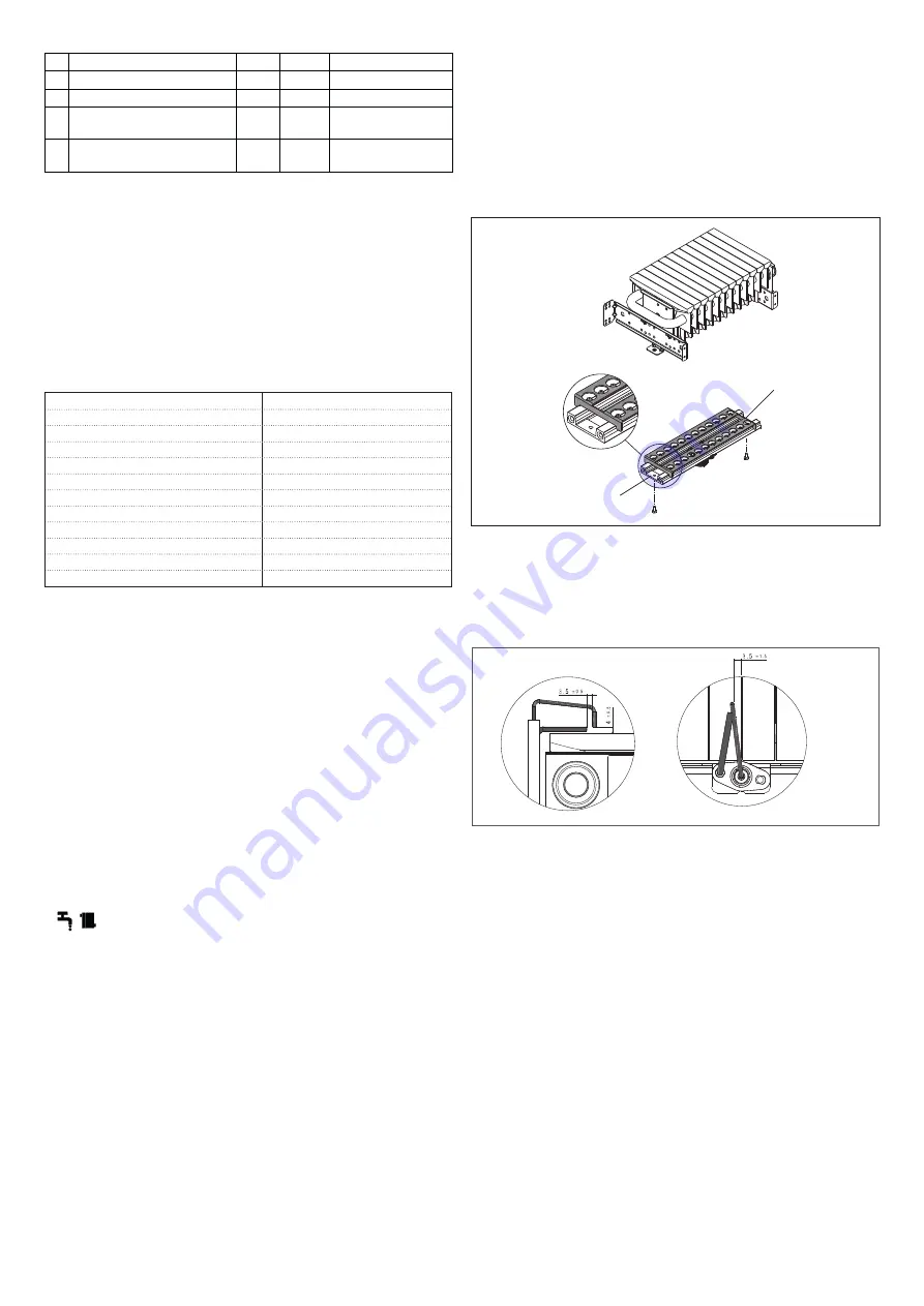
CONVERTION FROM NG TO LPG

- Disconnect the NG manifold from the burner by unscrewing the appropriate 

fi

 xing 

screws.

-  Take the LPG manifold and the 

fl

 ange from the appropriate conversion kit and, using the 

screws previously removed, fasten both to the burner.

CONVERTION FROM LPG TO NG

-  Disconnect the LPG manifold from the burner by unscrewing the appropriate 

fi

 xing screws.

-  Remove the LPG 

fl

 ange.

- Take the NG manifold from the appropriate conversion kit and, using the screws

previously removed, fasten both to the burner.

LPG 

fl

 ange

manifold

- Reposition the burner in its seat, 

fi

 xing the two support brackets with the 4 screws

previously removed to the bottom of the air box.

-  Reposition the spark plug and the support bracket, with the relative screws.

-  Reassemble carefully following the reverse procedure.

- Pay attention to the good condition of all seals and OR, making a general tightness

check.

- Reassemble the bracket with the spark plug, checking the correct position of the

electrode as shown in the 

fi

 gure.

-  Set parameter P01 as follows:

P01= 0 NG

P01= 1 LPG.

- After the gas transformation operations, proceed with a calibration of the gas valve as

described in paragraph "4.16.1 Auto-setting".

b

The transformation must be carried out only by quali

fi

 ed personnel.

b

At the end of the transformation, apply the new identi

fi

 cation plate contained in the kit. 

4.16 Adjustments

The boiler is supplied for operation with methane gas (G20) or LPG (G31) and is factory set 

as shown on the data plate.

b

Adjustments must be made in the sequence indicated and exclusively by the 

Technical Assistance Service.

b

Adjustments cannot be made if the boiler is in the OFF state.

-

Remove the casing by loosening the fastening screws.

-

Undo the 

fi

 xing screw of the instrument panel.

-

Loosen the screw of the pressure test point downstream from the gas valve by roughly

two turns, then connect the pressure gauge.

4.16.1  

Auto-setting

THIS PROCEDURE SHOULD ONLY BE CARRIED OUT IN THE FOLLOWING CASES: 

GAS VALVE REPLACEMENT, BOARD REPLACEMENT, GAS CONVERSION.

The gas valve does not provide for mechanical calibration: valve adjustments are therefore 

carried out electronically through two parameters q02 and q01.

-

Place the boiler in winter mode.

-

Referring to paragraph "4.11 Parameter access procedure (tS)" set parameter 

P19 = 1

then exit the procedure.

Содержание CIAO AT

Страница 1: ...Installer and user manual CIAO AT EN INSTALLER AND USER MANUAL PL INSTRUKCJA OBS UGI I INSTALACJI KOT A GAZOWEGO...

Страница 2: ...ained Instrukcja instalacji i u ytkowania 3 21 Elementy funkcyjne kot a 78 Schemat elektryczny 79 Grupa hydrauliczna 80 Wysoko podnoszenia pompy obiegowej 82 Kocio CIAO AT spe nia podstawowe wymagania...

Страница 3: ...the appliance from the main power supply by turning the system s main switch to OFF by setting the boiler to OFF a Do not modify the safety or adjustment devices without the manufacturer s authorisat...

Страница 4: ...for condensation exhaust connection This product is designed to prevent the escape of gaseous products of combustion through the condensation drain pipe with which it is equipped this is obtained by...

Страница 5: ...rticles b Once the appliance has been installed check the connections are sealed according to current installation regulations 3 11 Releasing the circulator Press the MODE button to select the OFF sta...

Страница 6: ...temperature adjustment increases the CH value decreases the CH value Domestic hot water DHW temperature adjustment increases the DHW value decreases the DHW value MODE Button for selecting summer wint...

Страница 7: ...peat this operation during routine and extraordinary maintenance operations MAX 50 mm 4 3 Operating modes Repeatedly pressing the MODE button displays in sequence the possible operating modes OFF WINT...

Страница 8: ...w supply voltage abnormal mains frequency A80 Fan defective or not connected fan wiring fault A34 CH NTC sensor over temperature A74 Fault A04 Low water pressure together with the error code the symbo...

Страница 9: ...ble or disable the preheating function At the beginning of the function the display shows FH and the pump starts immediately RESET RESET The display shows FH and On alternately Press RESET and CH to d...

Страница 10: ...applicable C 5 3 9 Not applicable to this model P21 Not applicable 0 0 1 0 disabled P22 if P21 1 Not applicable rpm x10 140 140 180 if P01 0 G20 1000 140 if P01 1 G31 P23 if P21 1 Not applicable rpm x...

Страница 11: ...em the procedure can be followed in DHW mode by turning on at least one hot water tap after activating the function as explained previously making sure that the DHW setpoint is set to the maximum valu...

Страница 12: ...em s general switch close the fuel and water taps of the heating and domestic hot water system To ensure that product characteristics and efficiency remain intact and compliance with current regulatio...

Страница 13: ...lockout symbol 6 2 Operating modes Repeatedly pressing the MODE button displays in sequence the possible operating modes OFF WINTER SUMMER CH ONLY DO NOT SET THIS CONFIGURATION OFF MODE MODE WINTER MO...

Страница 14: ...ture C 20 70 4 Burner output 0 100 5 Not used KOhm 0 99 6 Fan speed 0 3 0 Off 1 Min 2 Med 3 Max 7 Interval remaining before mainte nance 52 weeks To exit the Info menu press RESET for 1 second or pres...

Страница 15: ...II2H3P Voltage supply V Hz 230 50 Protection level IP X5D Losses at the flue with burner off burner on 0 12 3 78 Heating operation Pressure Maximum temperature bar C 3 90 Minimum pressure for standar...

Страница 16: ...in wall diameter mm 130 Twin flue gas outlet pipes Diameter mm 80 Maximum length m 14 14 Losses for a 45 90 bend m 1 1 5 Forced open installation B22P B52P Diameter mm 80 Maximum length m 14 Nox clas...

Страница 17: ...me P4 24 0 kW At 30 of rated heat output and low temperature regime P1 7 6 kW Useful efficiency At rated heat output and high temperature regime 4 86 1 At 30 of rated heat output and low temperature r...

Страница 18: ...personelem a Nie wolno dotyka urz dzenia b d c boso lub gdy cz ci cia a s mokre a Nie wolno wykonywa adnych rob t technicznych lub czyszczenia je eli urz dzenie nie zosta o od czone od sieci zasilani...

Страница 19: ...kocio nie przechowywa substancji atwopalnych atwo nagrzewaj ce si ciany np drewniane musz by pokryte w a ciw izolacj ochronn 3 6 Instrukcjapod czeniaprzewoduodprowadzeniakondensatu Produkt ten zosta z...

Страница 20: ...bokr tem jak pokazano na rys 2 W o y na miejsce korek i nacisn przycisk MODE tryb aby wybra dany tryb pracy b Aby unikn uszkodzenia element w podczas tej czynno ci nale y zachowywa najwy sz ostro no r...

Страница 21: ...C O zmniejszanie warto ci C O Regulacja temperatury ciep ej wody u ytkowej C W U zwi kszanie warto ci C W U zmniejszanie warto ci C W U MODE Przycisk wyboru funkcji LATO ZIMA WY CZONY Wej cie do trybu...

Страница 22: ...powoduje wy wietlanie dost pnych tryb w pracy WY CZONY OFF ZIMA LATO WY CZNIE C O NIE U YWA MODE MODE OFF WY MODE MODE ZIMA MODE MODE LATO Zima Aby aktywowa funkcj ZIMA nale y wciska przycisk MODE do...

Страница 23: ...ci nienia w uk adzie 1 i 1 5 bar ci g a obecno kodu b du A04 mo e by spowodowana interwencj ogranicznika ci nienia kondensatu zablokowany syfon lub odp yw kondensatu W takim przypadku konieczne jest...

Страница 24: ...podgrzewania jest dost pna w nast puj cych przypadkach po zablokowaniu spowodowanym nieprawid owo ci przez 10 sekund przy trwaj cym zapotrzebowaniu na ogrzewania podczas pracy pompy w trybie obiegu k...

Страница 25: ...1 P23 je eli P21 1 Nie dotyczy obr min x 10 100 100 140 je eli P01 0 G20 100 je eli P01 1 G31 P24 je eli P21 1 Nie dotyczy obr min x 10 110 110 140 je eli P01 0 G20 115 je eli P01 1 G31 b Parametry ko...

Страница 26: ...analiza tora spalin i ponownie za o y zdemontowane wcze niej elementy 4 15 Przezbrajanie na inny rodzaj gazu Przezbrojenie kot a z jednego rodzaju gazu na inny mo na przeprowadzi nawet po zainstalowa...

Страница 27: ...przepisami urz dzenie musi by poddawane systematycznym kontrolom w regularnych odst pach czasu Podczas konserwacji przestrzega instrukcji podanych w rozdziale 1 OSTRZE ENIA I BEZPIECZE STWO Zazwyczaj...

Страница 28: ...olejno przycisku MODE umo liwia wy wietlanie dost pnych tryb w pracy WY CZONY OFF ZIMA LATO WY CZNIE C O NIE U YWA OFF WY MODE MODE ZIMA MODE MODE LATO Zima Aby aktywowa funkcj ZIMA nale y wciska przy...

Страница 29: ...c palnika 0 100 5 Parametr nieu ywany kOhm 0 99 6 Pr dko wentylatora 0 3 0 Wy 1 Min 2 r 3 Maks 7 Czas pozosta y do konserwacji 52 tygodnie Aby wyj z menu informacji nacisn przycisk RESET na 1 sekund l...

Страница 30: ...eznaczenia II2E3P PL Napi cie zasilania V Hz 230 50 Poziom ochrony przeciwpora eniowej IP X5D Strata kominowa przy wy czonym palniku w czonym palniku 0 12 3 78 FUNKCJA C O Maksymalne ci nienie Tempera...

Страница 31: ...m 80 80 CO2 5 0 5 5 NOx b w poni ej p p m 20 25 Temperatura spalin C 60 62 U redniona warto z zakresu pracy w r nych warunkach Pr ba wykonana z koncentrycznym przewodem koncentrycznym 60 100 o d ugo...

Страница 32: ...o energetyczna ogrzewania pomieszcze s 87 Wytworzone ciep o u ytkowe Przy znamionowej mocy cieplnej i w systemie wysokotemperaturowym P4 24 0 kW Przy znamionowej mocy cieplnej na poziomie 30 i w syste...

Страница 33: ...way electric valve 26 Pressure gauge 27 Domestic hot water NTC sensor 16 27 12 PL Budowa kot a AF Wej cie z w AC Wyj cie c w u M Zasilanie c o R Powr t c o 1 Zaw r nape niania 2 Zaw r zwrotny 3 Zaw r...

Страница 34: ...Domestic hot water NTC sensor 7 Water pressure switch 8 Domestic hot water heat exchanger 9 Limit thermostat 10 Primary NTC sensor 11 Post exchanger thermal fuse 12 Capacitor 13 Primary heat exchange...

Страница 35: ...y Verde Zielony g v to zielony A Zworka TA OT styk bezpotencja owy BRT14 P yta steruj ca z wy wietlaczem cyfrowym i zintegrowanym transformatorem zap onowym F Bezpiecznik 3 15A F X1 X5 Z cza TR1 Trans...

Страница 36: ...36 8 EN Measured in mm PL Wymiary w mm 5 6 EN Indoor installation PL Monta wewn trz 7 9 50 50 93 5 65 47 75 73 75 65 60 1 4 0 M AC G AF R water gas woda gaz dimensions in mm wymiary w mm...

Страница 37: ...P 12 A B A B M4 S E t arancione arancione rosa rosa TA OT Contatto privo di tensione UWAGA Elementy systemu kominowego wraz ze schematami znajduj si w Katalogu Produkt w Beretta UWAGA Elementy systemu...

Страница 38: ...d11 B C A P13 Kd D 14 A B C D EN Graph 1 thermoregulation graph for main area with temperature range 35 80 C CH delivery temperature C Outdoor temperature C Graph 2 PL Wykres 1 wykres regulacji pogodo...

Страница 39: ...20176972 03 21 Ed 1 EN RANGE RATED EN 15502 The max CH input of this boiler has been adjusted to_____ kW equivalent to _____ rpm max CH fan speed Date___ ____ ____ Signature _____________________ Boi...

Отзывы: