Assembly and initial set-up
11
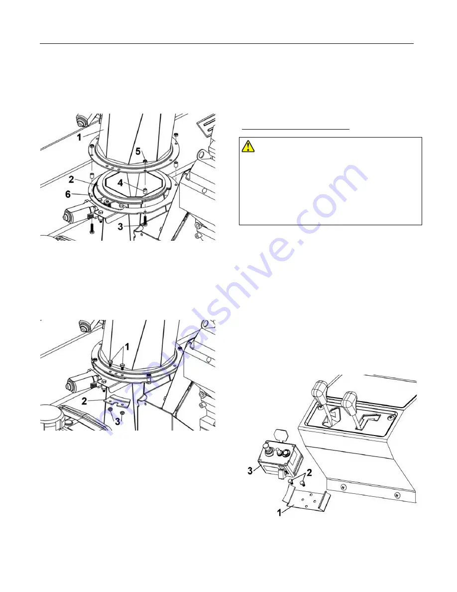
rotation ring (item 6) in each hole as shown.
c.
Insert the spacers (item 4) on the hex bolts
between the rotation ring and the chute. Secure
in place with the 1/4’’ nylon insert lock nuts
(item 5).
4.
Insert the 1/4’’ x 1/2’’ hex bolts (item 1) in the holes
as shown.
a.
Install the retaining plate (item 2) under the
chute as shown.
b.
Secure in place with the 1/4’’ nylon insert lock
nuts (item 3) as shown.
Control box installation:
DANGER
To prevent serious injury and even death
It is the user's responsibility to ensure that the electrical
harness is always in good condition and cannot be
damaged by any movement of the tractor or the
accessory or by sharp or too hot or abrasive surfaces.
1.
Disconnect the wires that are connected to the
control box (item 3).
2.
Install the box support (item 1) in an appropriate
place. Drill holes if necessary.
3.
Secure the box support with the two 1/4’’ x 1/2’’ hex
bolts and flange nuts.
4.
Tighten firmly.
5.
Install the control box on the box support.
6.
Thread the wires that unites the accessory under the
hood to the front of the vehicle.
7.
If necessary, reposition and tie the wires to the rear
of the snowblower and the hitch frame without
touching the electrical connection.
Содержание 700968-1-33V
Страница 8: ...Important safety information 6 Decal 109032 2 places...
Страница 32: ...Part list and parts breakdown 30 Part list and parts breakdown...
Страница 33: ...Part list and parts breakdown 31...
Страница 35: ...Part list and parts breakdown 33...
Страница 38: ...Part list and parts breakdown 36...
Страница 41: ...Part list and parts breakdown 39...
Страница 44: ...Part list and parts breakdown 42...
Страница 47: ...Part list and parts breakdown 45...
Страница 49: ...Part list and parts breakdown 47...
Страница 51: ...Part list and parts breakdown 49...
Страница 53: ...Part list and parts breakdown 51...


