2
Product Number: QG0014-01 Revision: A0; Date: 4/29/13
The power supplies are removable (replaceable) from the rear
of the frame. The system controllers are removable (replace-
able) from the front of the frame.
If you have an NV920S (single controller) the empty second-
ary bay will have a blank front plate.
The System Controller
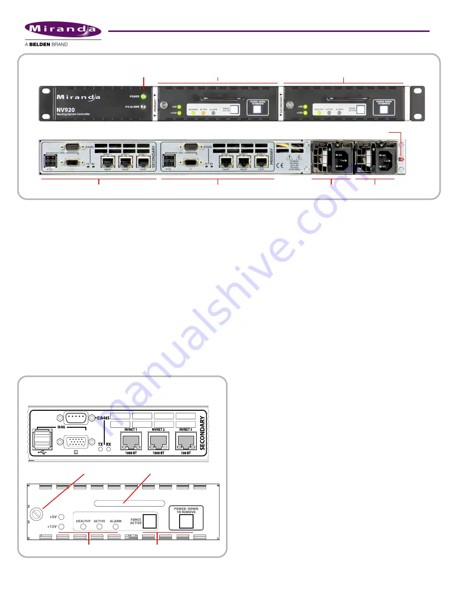
At the rear of the NV920 frame are two identical sets of con-
nectors, one for each system controller. See Figure 3.
Among these are 3 Ethernet (RJ-45) connectors. Two support
1G Ethernet. The third supports 100M Ethernet. The Ether-
net ports are otherwise identical. At least one must be used
for a panel and router network. One must be connected to
your “house network” for configuration and monitoring.
Two USB ports and a VGA port allow you to connect a key-
board, mouse, and monitor to the system controller. (The sys-
tem controller runs Windows XP embedded, so you can
perform diagnostic and maintenance tasks using XP’s normal
Windows desktop.) You can also use the USB ports to update
the system controller’s software.
The “EIA-485” connector (DE9) supports the control of one
serial device. The port’s pinout is the same as that of a Moxa
CP-118U. You can use a WC0137 “Y” cable to connect the two
system controllers of an NV920 to the device you are control-
ling. The “Y” cable forms a redundant connection.
There are Tx and Rx status LEDs for the serial port that illumi-
nate when the port is transmitting and receiving, respec-
tively.
There are also cooling fans at the rear of each system control-
ler. The rear of the NV920 frame has grill openings that vent
the exhaust from the fans.
Each system controller is removable. At the left side at the
front of the system controller is a latch. Turn the latch a quar-
ter turn to lock the system controller in place. Turn the latch
in the other direction to remove the system controller.
Use the handle of the system controller to pull it out of its bay
(or to carry it).
The large button (backlit, white) at the right is labeled “Power
Down to Remove.” It is important to power the system con-
troller off before removing it. When the system controller is
powered up, the 2 green LEDs (l5V and +12V), the 3
status LEDs, and the 2 white buttons illuminate. When the
system controller’s software finishes initializing, the alarm
LED goes out.
There are 3 status LEDs in the middle of the front of the sys-
tem controller:
•
Healthy. This LED is green (on) when the system control-
ler is running properly. If the NV920 frame has two system
controllers, the health LED is normally on for both.
•
Active. This LED is amber (yellow) when the system con-
troller is the active controller. When the NV920 frame has
two system controllers, the LED is on only for the one con-
troller that is active.
Figure 2. NV920
Primary System Controller
Secondary System Controller
Connectors for Secondary System Controller
Connectors for Primary System Controller
Front View
Rear View
PS 2
PS 1
Power LEDs
Power Failure Alarm Mute Button
Figure 3. System Controller
Front View
Rear (Panel) View
Latch
Handle
LEDs
Buttons


