FLIPPING™ ARCH
1MANUL027
Belanger®, Inc. *PO BOX 5470 *Northville, MI 48167-5470 * Ph (248) 349-7010 * Fax (248) 380-9681
15
Installation
Arch Assembly
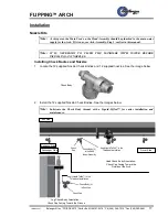
4. Secure the Main Feed Block to the top of the Head Assembly, it can be mounted to either the
driver side or passenger side of the Head Assembly.
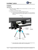
5. Locate the appropriate Main Feed Connection and the 3/4" MNPT Plug. See the images
below.
Note:
There are 3 options for the Main Feed Connection. All 3 are installed in the same location.
Note:
The standard Single Feed Connection is shown installed in the Head Assembly below.
Note:
The other 2 possibilities for the Main Feed are optional. These options are the Dual Feed
and Check Valve Connections.
Install the Main Feed Connection into the Head Assembly on the Equipment Room side of
the Arch. Then install the 3/4" MNPT Plug on the opposite side of the Head Assembly.
Install the Main Feed Kit from the Main Feed Block to the Head Beam Manifold Assembly
Note:
Apply Teflon™ tape and Liquid Teflon™ to the pipe threads at installation.
Main Feed Connection
3/4" MNPT
Plug
Single Feed
3/4" MNPT with
3/4" Hose Barb
Dual Feed
3/4" MNPT with
(2) 3/4" Hose Barbs with
Check Valves
Inlet Check Valve
3/4" MNPT with
(1) 1/2" Poly-Flow Tube Connection
with a Check Valve and
(1) 1/4" Poly-Flow Tube Connection
with a Check Valve
*
*
Direction
Of Travel
Head
Assembly
View of the Head Assembly for a Passenger Side Equipment Room
3/4" MNPT
Plug
Driver Side
Passenger Side
Single Feed
Assemb
ly
Entrance Side
Exit Side
3/8”-16 x 2-1/2 Hex Head Cap Screw (2)
and 3/8” Lock Washer (2)
Rotated view of the Head
Assembly in order to see the
manifold.
Main Feed Kit


