ITALIANO
ENGLISH
MICROTEC 810
16
COD. 653628 Rev.0
SELEZIONE PROGRAMMA DI EQUILIBRATURA
L’impiego di diversi tipi di contrappesi per l’equilibratura dei vari tipi di cerchi
(in acciaio o in lega leggera) produce delle differenze tra le misure nominali
impostate per la ruota da equilibrare e le misure effettive dei piani di
correzione. L’equilibratrice utilizza diversi programmi di equilibratura per te-
nere conto di queste differenze.
L’operatore deve impostare la modalità di funzionamento desiderata in base
al tipo di ruota da equilibrare, ai contrappesi che intende utilizzare ed ai
piani di correzione prescelti.
Premendo il tasto MODE si accede in sequenza a tutti i diversi programmi di
equilibratura disponibili che sono:
»
equilibratura dinamica standard
con pesi a clip (con molletta),
»
5 programmi Alu
per l’equilibratura dinamica con pesi adesivi,
»
3 programmi di
equilibratura statica
(con pesi a molletta o adesivi),
»
2 programmi Alu
speciali per l’equilibratura dei pneumatici PAX Michelin
con pesi adesivi e misure in mm.
I led del pannello comandi indicano la posizione dei contrappesi sul cerchio
in base al programma di equilibratura prescelto.
All’accensione la macchina si configura automaticamente in programma
dinamica standard.
IMPOSTAZIONE DATI RUOTA
Impostare sul pannello frontale i valori della
larghezza
(tasti
(6)
in
fig.19
),
diametro
(tasti
(5)
in
fig.19
)
e
distanza
(tasti
(4)
in
fig.19
), della ruota su
cui si deve operare:
»
la misura relativa alla
larghezza cerchio
è in genere riportata sul cerchio
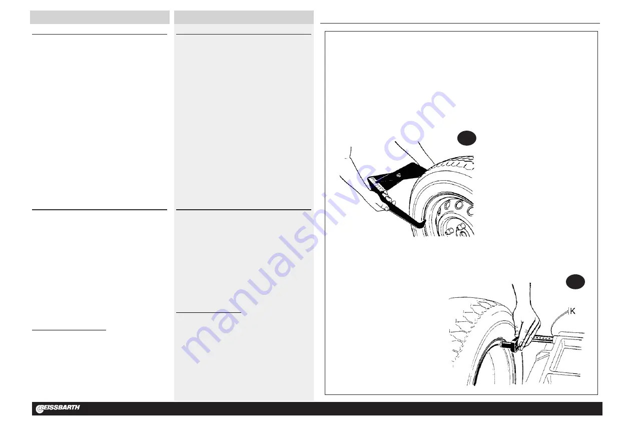
stesso oppure si ricava misurandola con il calibro in dotazione alla
macchina (
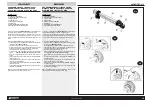
fig. 20a
);
»
il
diametro del cerchio
è in genere riportato sul cerchio stesso oppure
può essere letto sul pneumatico;
»
la
distanza cerchio
viene misurata sul fianco interno del cerchio con il
calibro a corsoio installato sulla macchina (
fig. 20b
), e dalla scala si può
leggere la distanza da impostare.
N.B.
: per ruote di piccole dimensioni (per esempio ruote di motociclo) deve
essere determinato solo lo squilibrio statico; in questi casi si utilizza il pro-
gramma di equilibratura STATICA e si deve impostare il valore corretto del
solo diametro cerchio
(tasti
(5)
in
fig.19
); le misure di
distanza e larghezza
cerchio
possono essere impostate su qualsiasi valore.
INSERIMENTO DELLE MISURE IN mm
L’unità di misura predefinita per larghezza e diametro cerchio è pollici.
Per impostare le misure della ruota in mm occorre premere il tasto MM/INCH
e inserire le misure in millimetri così come si leggono sulla ruota.
Il led acceso indica che la misura selezionata è impostata in mm.
La distanza è sempre impostata in mm (led acceso).
N.B.
: per i programmi PAX l’unità di misura predefinita per larghezza e
diametro cerchio è mm.
SELECTION OF BALANCING PROGRAM
The use of various types of counterweights for balancing the various types
of rims (steel or light alloy) produces differences between nominal measure-
ments set for the wheel being balanced and the measurements of the refer-
ence planes. The balancer uses various balancing programs to take account
of these differences.
The operator sets the operation mode desired on the basis of the type of
wheel to be balanced, the counterweights to be used and the preselected
reference planes.
Press the MODE key to access the various available balancing programs,
namely:
»
standard dynamic balancing
with clip weights,
»
5 Alu programs
for dynamic balancing using adhesive weights,
»
3 static balancing programs (with clip or adhesive weights),
»
2
special
Alu
programs
for PAX Michelin tyre balancing with adhesive
weights and mm measurements.
The control panel LEDs indicate the position of the weights on the rim on the
basis of the preselected balancing program.
On start-up the machine automatically configures on the standard dynamic
program.
SETTING WHEEL DATA
Set the following on the front panel:
width
(keys
(6)
in
fig.19
),
diameter
(keys
(5)
in
fig.19
)
and
distance
(keys
(4)
in
fig.19
), all relating to the wheel
to be balanced:
» the
rim width
measurement is generally etched on the rim itself, or can
be obtained using the gauge supplied with the machine (
fig. 20a
);
» the
rim diameter
is generally etched on the rim itself, or is on the tyre;
» the
rim distance
is measured on the internal side of the rim with the
sliding gauge installed on the machine (
fig. 20b
), and using the scale to
read the distance to set.
N.B.
: for small-dimension wheels (e.g. motorcycle wheels) only static unbal-
ance needs to be determined, using the STATIC balancing program and set-
ting the right value for
only the rim diameter
(keys
(5)
in
fig.19
); the
rim
distance and width
measurements can be set to any value.
ENTERING MM MEASUREMENTS
The preset unit of measurement for rim width and diameter is the inch.
To set the wheel measurements to mm press the MM/INCH key and enter
measurements in millimetres, as etched on the wheel itself.
The LED lights up to indicate that measurements are set to millimetres.
The distance is always set in mm (lit LED).
N.B.
: for PAX programs the preset unit of measurement for width and diam-
eter is mm.
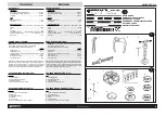
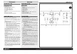
20b
20a
K = punto di Lettura
K = reading point
K = point de lecture
K = Ablesestelle
K = punto de Lectura
K = òî÷êà ÷òåíèÿ
Содержание MICROTEC 810
Страница 44: ...MICROTEC 810 N 653332 Rev 2 ...
Страница 45: ...MICROTEC 810 N 653333 Rev 3 ...
Страница 48: ...OPTIONAL N 653334 Rev 1 ...
Страница 49: ......

