


4–8
M‑3425A Instruction Book
USER LOGO LINE
The user logo is a programmable, two-line by
24-character string, which can be used to identify the
relay, and which is displayed locally when the unit is
idle. This information is also available in IPScom
®
.
USER CONTROL NUMBER
The User Control Number is a user-defined value
which can be used for inventory or identification.
The unit does not use this value, however, it can be
accessed through the HMI or the communications
interface, and can also be read remotely.
SYSTEM OK LED
The green
SYSTEM OK
LED is controlled by the
unit’s microprocessor. A flashing
SYSTEM OK
LED
indicates proper program cycling. The LED can
also be programmed to be continuously illuminated
indicating proper program cycling.
IPScom User Logo Line, User Control Number,
System OK LED Setup and HMI Blanking
To set the relay User Logo Lines, User Control
Number, System OK LED and HMI Blanking
perform the following:
NOTE
: Communication must be established with
the target relay for this procedure.
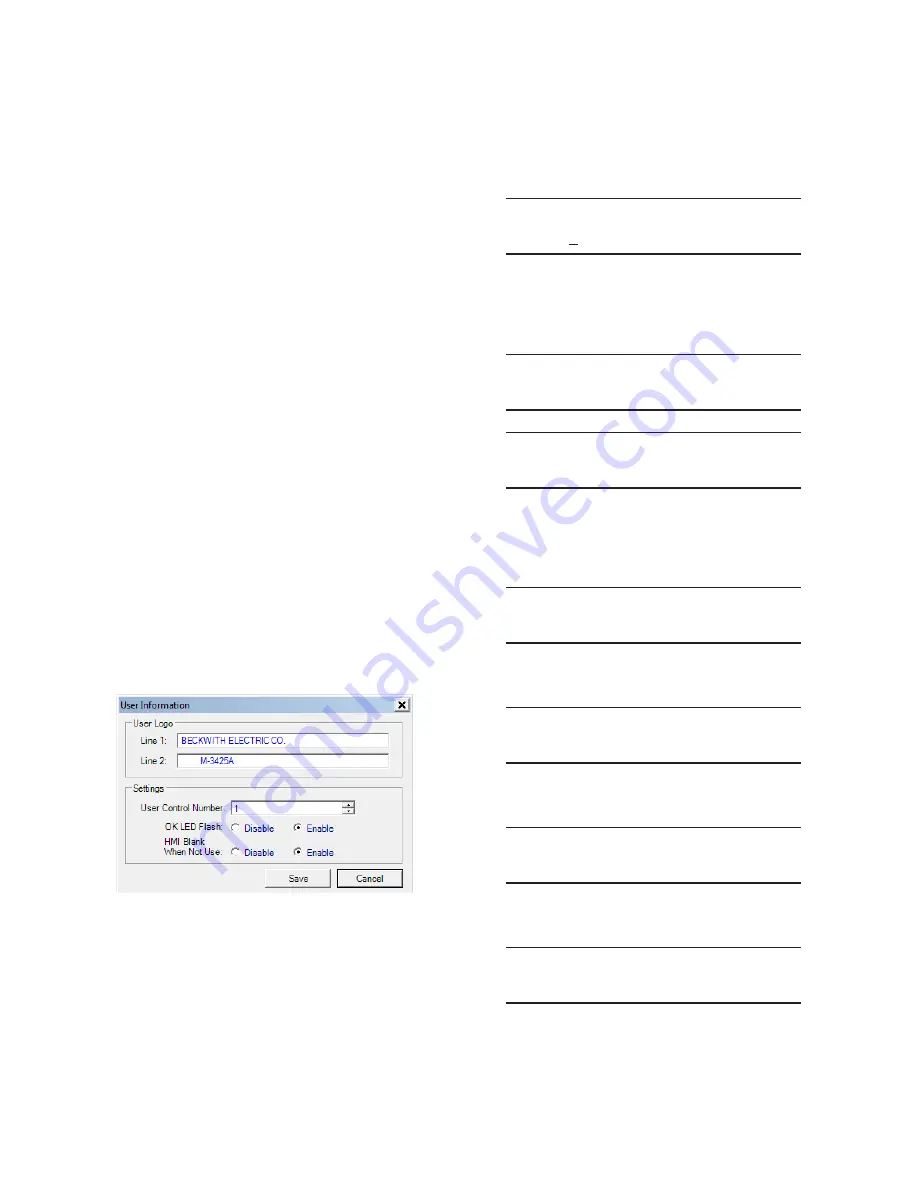
1.
From the IPScom Main Screen menu
select
Tools/User Information
. IPScom
will display the User Information dialog
screen (Figure 4-6).
Figure 4-6
User Information Dialog Screen
2.
If entering/editing the User Logo lines,
then enter the desired User Logo Lines.
3.
If changing the User Control Number, then
enter the desired User Control Number.
4.
If enabling/disabling the System OK
LED Flash operation, then select either
Enable
or
Disable
.
5. Select
Save
, IPScom will return to the
Main Screen.
HMI User Logo Line Setup
1.
Press the
ENTER
pushbutton.
2.
If Level Access is active, the following is
displayed:
ENTER ACCESS CODE
0
a.
Input the required Access Code, then
press
ENTER
.
b. If the proper Access Code has been
entered, the HMI will return:
LEVEL #(1,2 or 3)
Access Granted!
VOLTAGE RELAY
VOLT curr freq v/hz
V
c.
Go to step 4.
3.
If Level Access is not active, then the
following is displayed:
VOLTAGE RELAY
VOLT curr freq v/hz
V
4.
Press the Right arrow pushbutton until
the following is displayed:
SETUP UNIT
SETUP
5. Press
ENTER
, the following will be
displayed:
SOFTWARE VERSION
VERS sn access number
V
6.
Press the Right arrow pushbutton until
the following is displayed:
USER LOGO LINE 1
LOGO 1 logo 2 alrm
V
Содержание M-3425A
Страница 1: ...Instruction Book M 3425A Generator Protection ...
Страница 38: ...This Page Left Intentionally Blank ...
Страница 39: ...800 3425A SP 10MC2 07 12 2001 Beckwith Electric Co All Rights Reserved Printed in U S A 01 67 04 25 03 ...
Страница 43: ...This Page Left Intentionally Blank ...
Страница 57: ...xiv M 3425A Instruction Book This Page Left Intentionally Blank ...
Страница 63: ...M 3425A Instruction Book 1 6 This Page Left Intentionally Blank ...
Страница 73: ...M 3425A Instruction Book 2 10 Path Monitor Primary Metering Status Figure 2 4 Primary Metering Status Screen ...
Страница 95: ...M 3425A Instruction Book 2 32 This Page Left Intentionally Blank ...
Страница 97: ...M 3425A Instruction Book 3 2 Figure 3 2 IPScom Main Screen ...
Страница 103: ...M 3425A Instruction Book 3 8 Path Monitor Primary Metering and Status Figure 3 9 Primary Metering Status Screen ...
Страница 105: ...M 3425A Instruction Book 3 10 Path Monitor Secondary Metering and Status Figure 3 10 Secondary Metering Status Screen ...
Страница 123: ...M 3425A Instruction Book 3 28 Figure 3 30 View Sequence of Events Recorder Screen ...
Страница 131: ...M 3425A Instruction Book 3 36 This Page Left Intentionally Blank ...
Страница 162: ...4 31 System Setup and Setpoints 4 Figure 4 15 IPScom Relay Setup System Dialog Screen ...
Страница 180: ...4 49 System Setup and Setpoints 4 Table 4 5 Impedance Calculation Figure 4 30 Phase Distance 21 Setpoint Ranges ...
Страница 183: ...4 52 M 3425A Instruction Book Figure 4 32 Volts Per Hertz 24 Setpoint Ranges ...
Страница 187: ...4 56 M 3425A Instruction Book Figure 4 34 Sync Check 25 Setpoint Ranges ...
Страница 202: ...4 71 System Setup and Setpoints 4 Figure 4 50 49 Function Overload Curves ...
Страница 203: ...4 72 M 3425A Instruction Book Figure 4 51 Stator Thermal Protection 49 Setpoint Ranges ...
Страница 215: ...4 84 M 3425A Instruction Book Figure 4 62 Phase Overvoltage 59 Setpoint Ranges ...
Страница 219: ...4 88 M 3425A Instruction Book Figure 4 65 Overvoltage Neutral Circuit or Zero Sequence 59N Setpoint Ranges ...
Страница 236: ...4 105 System Setup and Setpoints 4 Figure 4 77 Residual Directional Overcurrent 67N Setpoint Ranges ...
Страница 239: ...4 108 M 3425A Instruction Book Figure 4 80 Out of Step 78 Setpoint Ranges ...
Страница 242: ...4 111 System Setup and Setpoints 4 Figure 4 82 Frequency 81 Setpoint Ranges ...
Страница 261: ...M 3425A Instruction Book 5 6 Figure 5 5 Mounting Dimensions for GE L 2 Cabinet H3 and H4 ...
Страница 277: ...M 3425A Instruction Book 5 22 Figure 5 14 M 3425A Circuit Board ...
Страница 278: ...Installation 5 5 23 Figure 5 15 M 3425A Circuit Board Expanded I O ...
Страница 280: ...Installation 5 5 25 Figure 5 17 20 Hz Frequency Generator Housing Panel Surface Mount ...
Страница 281: ...M 3425A Instruction Book 5 26 Figure 5 18 20 Hz Frequency Generator Housing Panel Flush Mount ...
Страница 282: ...Installation 5 5 27 Figure 5 19 20 Hz Band Pass Filter Housing Panel Surface Mount ...
Страница 283: ...M 3425A Instruction Book 5 28 Figure 5 20 20 Hz Band Pass Filter Housing Panel Flush Mount ...
Страница 284: ...Installation 5 5 29 Figure 5 21 20 Hz Measuring Current Transformer 400 5 A CT ...
Страница 421: ...D 2 M 3425A Instruction Book Figure D 1 Volts Hz 24 Inverse Curve Family 1 Inverse Square ...
Страница 422: ...Inverse Time Curves Appendix D D 3 Figure D 2 Volts Hz 24 Inverse Family Curve 2 ...
Страница 423: ...D 4 M 3425A Instruction Book Figure D 3 Volts Hz 24IT Inverse Curve Family 3 ...
Страница 424: ...Inverse Time Curves Appendix D D 5 Figure D 4 Volts Hz 24IT Inverse Curve Family 4 ...
Страница 427: ...D 8 M 3425A Instruction Book Figure D 5 BECO Definite Time Overcurrent Curve ...
Страница 428: ...Inverse Time Curves Appendix D D 9 Figure D 6 BECO Inverse Time Overcurrent Curve ...
Страница 429: ...D 10 M 3425A Instruction Book Figure D 7 BECO Very Inverse Time Overcurrent Curve ...
Страница 430: ...Inverse Time Curves Appendix D D 11 Figure D 8 BECO Extremely Inverse Time Overcurrent Curve ...
Страница 437: ...D 18 M 3425A Instruction Book Figure D 15 IEEE Extremely Inverse Time Overcurrent Curves ...
Страница 469: ...F 30 M 3425A Instruction Book This Page Left Intentionally Blank ...
Страница 479: ...H 2 M 3425A Instruction Book This Page Left Intentionally Blank ...
Страница 481: ...This Page Left Intentionally Blank ...