background image

Commissioning

EL922x

99

Version: 1.0

Fig. 101: Basic EtherCAT Slave Diagnosis in the PLC

The following aspects are covered here:

Содержание EL922 Series

Страница 1: ...Documentation EL922x Electronic overcurrent protection terminals 1 0 2018 11 23 Version Date...

Страница 2: ......

Страница 3: ...ystem 35 6 3 2 Wiring 36 6 4 Prescribed installation position 38 6 5 Installation instructions for enhanced mechanical load capacity 39 6 6 Positioning of passive Terminals 40 6 7 LEDs and pin assignm...

Страница 4: ...basic principles of diag messages 148 8 2 Text ID s EL922x 151 9 Appendix 152 9 1 EtherCAT AL Status Codes 152 9 2 Firmware compatibility 152 9 3 Firmware Update EL ES EM EPxxxx 154 9 3 1 Device desc...

Страница 5: ...A EL9222 6600 Overcurrent protection terminal 14 2 channel IN adjustable up to 4 A EL9222 6644 Overcurrent protection terminal 14 2 channel IN 4 A 4 A EL9222 9482 Overcurrent protection terminal 14 2...

Страница 6: ...diagrams and descriptions in this documentation Trademarks Beckhoff TwinCAT EtherCAT EtherCAT P Safety over EtherCAT TwinSAFE XFC and XTS are registered trademarks of and licensed by Beckhoff Automat...

Страница 7: ...ined specialists in control automation and drive engineering who are familiar with the applicable national standards Description of instructions In this documentation the following instructions are us...

Страница 8: ...Foreword EL922x 8 Version 1 0 2 3 Documentation issue status Version Comment 1 0 1st public issue Complements corrections 0 2 0 9 3 Complements corrections 0 1 Provisional documentation for EL922x...

Страница 9: ...eckhoff In principle a device with a higher revision can replace a device with a lower revision unless specified otherwise e g in the documentation Associated and synonymous with each revision there i...

Страница 10: ...ardware version of the I O PCB Example D 22081501 calendar week 22 of the year 2008 firmware version of bus PCB 1 hardware version of bus PCB 5 firmware version of I O PCB 0 no firmware necessary for...

Страница 11: ...1 Version 1 0 Fig 3 EK1100 EtherCAT coupler standard IP20 IO device with serial batch number Fig 4 CU2016 switch with serial batch number Fig 5 EL3202 0020 with serial batch number 26131006 and unique...

Страница 12: ...r 158102 Fig 7 EP1908 0002 IP67 EtherCAT Safety Box with batch number date code 071201FF and unique serial number 00346070 Fig 8 EL2904 IP20 safety terminal with batch number date code 50110302 and un...

Страница 13: ...vercurrents The nominal current can be set in 1 A steps up to 10 A either via TwinCAT or via a mechanical pushbutton on the overcurrent protection terminal In addition there are further versions of th...

Страница 14: ...he EL9222 xxxx has standard functionalities i e the following setting options and process data are available Settings Nominal current LED button programming function Process data Enabled tripped prewa...

Страница 15: ...ad instantaneous current input voltage and output voltage Furthermore it can be used flexibly since numerous settings are available individually e g nominal current characteristics manual characterist...

Страница 16: ...rrent limitation typically 25 A for 20 ms typically 10 A for 50 ms typically 10 A for 50 ms typically 10 A for 50 ms typically 16 A for 30 ms typically 16 A for 30 ms typically 25 A for 20 ms Switch o...

Страница 17: ...r 50 ms Max current limitation channel1 channel2 typically 25 A for 20 ms typically 25 A for 20 ms typically 10 A for 50 ms typically 10 A for 50 ms typically 10 A for 50 ms typically 10 A for 50 ms t...

Страница 18: ...pically 10 A for 50 ms typically 10 A for 50 ms typically 10 A for 50 ms typically 10 A for 50 ms typically 10 A for 50 ms typically 10 A for 50 ms typically 16 A for 30 ms typically 10 A for 50 ms ty...

Страница 19: ...tandard slow t in ms 1 1 7 000 10 000 15 000 1 2 7 000 10 000 15 000 1 3 3 500 5 000 7 500 1 4 3 500 5 000 7 500 1 5 700 1 000 1 500 1 6 700 1 000 1 500 1 7 700 1 000 1 500 1 8 70 100 150 1 9 70 100 1...

Страница 20: ...tion of the power dissipation limitation refers to the internal power dissipation in the terminal The value of the power dissipation limitation is fixed whereas the current flow depends on the voltage...

Страница 21: ...802 3 Pin Color of conductor Signal Description 1 yellow TD Transmission Data 2 orange TD Transmission Data 3 white RD Receiver Data 6 blue RD Receiver Data Due to automatic cable detection auto cross...

Страница 22: ...l for longer than the set and activated SM watchdog time e g in the event of a line interruption the watchdog is triggered and the outputs are set to FALSE The OP state of the terminal is unaffected T...

Страница 23: ...the checkbox is not activated nothing is downloaded and the ESC settings remain unchanged Multiplier Multiplier Both watchdogs receive their pulses from the local terminal cycle divided by the watchdo...

Страница 24: ...witching off of the SM watchdog via SM watchdog 0 is only implemented in terminals from version 0016 In previous versions this operating mode should not be used CAUTION Damage of devices and undefined...

Страница 25: ...tional Safe Op During transition between Pre Op and Safe Op the EtherCAT slave checks whether the sync manager channels for process data communication and if required the distributed clocks settings a...

Страница 26: ...ation values for analog measurement or passwords The order is specified in 2 levels via hexadecimal numbering main index followed by subindex The value ranges are Index 0x0000 0xFFFF 0 65535dez SubInd...

Страница 27: ...ters are still available after a restart The situation may be different with other manufacturers An EEPROM is subject to a limited lifetime with respect to write operations From typically 100 000 writ...

Страница 28: ...is to be stored permanently enter it in the Startup list The order of the Startup entries is usually irrelevant Fig 17 Startup list in the TwinCAT System Manager The Startup list may already contain v...

Страница 29: ...The actual current slave list is read This may take several seconds depending on the size and cycle time The actual identity is displayed The firmware and hardware version of the equipment according t...

Страница 30: ...placeholder n tends to be used for the individual channel numbers In the CoE system 16 indices each with 255 subindices are generally sufficient for representing all channel parameters The channel bas...

Страница 31: ...c film etc Surroundings working place packaging and personnel should by grounded probably when handling with the devices Each assembly must be terminated at the right hand end with an EL9011 or EL9012...

Страница 32: ...oupler Join the compo nents with tongue and groove and push the terminals against the mounting rail until the lock clicks onto the mounting rail If the terminals are clipped onto the mounting rail fir...

Страница 33: ...ents The six spring contacts of the K Bus E Bus deal with the transfer of the data and the supply of the Bus Terminal electronics The power contacts deal with the supply for the field electronics and...

Страница 34: ...ting or to damage on the terminal e g disruptive discharge to the PE line during insulation testing of a consumer with a nominal voltage of 230 V For insulation testing disconnect the PE supply line a...

Страница 35: ...ity Standard wiring ELxxxx KLxxxx Fig 24 Standard wiring The terminals of ELxxxx and KLxxxx series have been tried and tested for years They feature integrated screwless spring force technology for fa...

Страница 36: ...sign as the packaging density is twice as large as that of the standard 12 mm Bus Terminals Massive conductors and conductors with a wire end sleeve can be inserted directly into the spring loaded ter...

Страница 37: ...wire size width Terminal housing ELxxxx KLxxxx ESxxxx KSxxxx Wire size width single core wires 0 08 2 5 mm2 0 08 2 5 mm2 Wire size width fine wire conductors 0 08 2 5 mm2 0 08 2 5 mm2 Wire size width...

Страница 38: ...below the terminal in order to guarantee adequate ventilation Prescribed installation position The prescribed installation position requires the mounting rail to be installed horizontally and the conn...

Страница 39: ...load capacity the following additional installation instructions apply The enhanced mechanical load capacity is valid for all permissible installation positions Use a mounting rail according to EN 607...

Страница 40: ...not take an active part in data transfer within the bus terminal block are so called passive terminals The passive terminals have no current consump tion out of the E Bus To ensure an optimal data tra...

Страница 41: ...V power supply 2 24 V DC input voltage internally connected to terminal point 6 0 V power supply 3 0 V DC input voltage internally connected to terminal point 7 and power contact 0 V 4 Not used Protec...

Страница 42: ...AT State Machine BOOTSTRAP function for terminal firmware up dates 154 Ready LED Ready LED indicates the status for overcurrent protection programming mode query mode Green on 24 V DC supply voltage p...

Страница 43: ...han 5x OFF applies Long press 3s Saving the nominal current value and leaving the programming mode No operation for 45 seconds After 45 seconds the programming mode is automatically exited without sav...

Страница 44: ...power supply 3 0 V DC input voltage internally connected to terminal point 7 and power contact 0 V Digital input 2 4 Digital input for switching output 2 negative edge 0 V reference as supply Protect...

Страница 45: ...distributed clocks The outputs remain in safe state on State of the EtherCAT State Machine OP normal operating state mailbox and process data communication is possible flickering State of the EtherCAT...

Страница 46: ...e two buttons in operation mode for 3 seconds For operation in the respective modes please refer to the table LED buttons Operation Programming Button LED Operation Programming LED State Meaning Opera...

Страница 47: ...L9222 5500 has a sum current limitation of 10 A The 10 A can be split between the two channels If one channel is set to 10 A the other channel must be set to OFF If the sum current is exceeded button...

Страница 48: ...power supply 3 0 V DC input voltage internally connected to terminal point 7 and power contact 0 V Digital input 2 4 Digital input for switching output 2 negative edge 0 V reference as supply Protect...

Страница 49: ...hine BOOTSTRAP function for terminal firmware updates 154 Status LED 1 Status LED 1 shows additional information for output 1 Orange on Output 1 has detected undervoltage or overvoltage Red flashing C...

Страница 50: ...he two buttons in operation mode for 3 seconds For operation in the respective modes please refer to the table LED buttons Operation Programming Button LED Operation Programming LED State Meaning Oper...

Страница 51: ...L9227 5500 has a sum current limitation of 10 A The 10 A can be split between the two channels If one channel is set to 10 A the other channel must be set to OFF If the sum current is exceeded button...

Страница 52: ...which case the settings made previously are not saved In other words the previously saved settings are retained 5 The nominal currents are changed by entering the absolute current values I e 1 x press...

Страница 53: ...Button LED 1 flashes 6x green Button LED 2 flashes 4x green Programming mode is active Output 1 is set to 6 A Output 2 is set to 4 A Press button LED 1 7x Output 1 is set to 7 A Ready LED lights up or...

Страница 54: ...out changing the parameters the terminals are set to the factory settings Table 4 Factory settings EL9221 EL9222 EL9227 5000 6000 5500 6600 5500 6600 Nominal Current 4 A 4 A 2 A 2 A 4 A 4 A 2 A 2 A 4...

Страница 55: ...ne to prevent automatic restarting of plant components see Machinery Directive 2006 42 EC and EN60204 1 Only modify these output values if you are certain that the state of your equipment permits it a...

Страница 56: ...Fig 35 Exemplary wiring of an input voltage of the EL9221 5000 to another terminal 3 Nominal current setting Use button LED 1 or button LED 2 to set the desired nominal current Programming sequence P...

Страница 57: ...ng with LED buttons 41 4 Commissioning The EL922x is ready for operation when the green Ready LED lights up after successful nominal cur rent setting and initialization Checking of the process data ha...

Страница 58: ...or 7 The maximum permissible input current in case of forwarding the input voltage can be found in the technical data Input current forwarding current current of the own terminal Protected output Con...

Страница 59: ...ration using the LED buttons 41 as described in chap ter Mounting and wiring 41 Checking of the process data hardware protection and the Diag messages Check the process data 106 hardware protection an...

Страница 60: ...e a safe state in the case of a bus error The safe state of the output in the case of a bus error is defined with DIG Safe State Value index 0x80n1 01 1 DIG Safe State Active TRUE and DIG Safe State V...

Страница 61: ...they can still be switched via the LED but tons and the digital inputs Settings via the Settings tab In a more compact display the settings can also be entered via the Settings tab Proceed as follows...

Страница 62: ...init state input functions overvoltage behavior undervoltage reverse current filter channel delay and manual characteristic The active characteristic area is not an input mask value field highlighted...

Страница 63: ...The settings can be imported or exported via this button Product Details Here you can find information such as a product image with connection instructions Default Values Pressing this button loads th...

Страница 64: ...tomation Visual Studio Integration Choice of the programming language Supports object orientated extension of IEC 61131 3 Usage of C C as programming language for real time applications Connection to...

Страница 65: ...s listed under Compatible devices can be assigned a driver via the Install button A driver should only be installed on compatible devices A Windows warning regarding the unsigned driver can be ignored...

Страница 66: ...s of the EtherCAT device can be opened by double click on Device EtherCAT within the Solution Explorer under I O After the installation the driver appears activated in the Windows overview for the net...

Страница 67: ...Commissioning EL922x 67 Version 1 0 Fig 47 Exemplary correct driver setting for the Ethernet port Other possible settings have to be avoided...

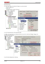
Страница 68: ...Commissioning EL922x 68 Version 1 0 Fig 48 Incorrect driver settings for the Ethernet port...

Страница 69: ...here an EL6601 or similar devices are used it is useful to specify a fixed IP address for this port via the Internet Protocol TCP IP driver setting and to disable DHCP In this way the delay associated...

Страница 70: ...was current at the time when the TwinCAT build was created For TwinCAT 2 11 TwinCAT 3 and higher the ESI directory can be updated from the System Manager if the programming PC is connected to the Inte...

Страница 71: ...on 1019 or for an older revision The ESI must then be requested from the manufacturer in this case Beckhoff b an ESI is present for the EL2521 0000 device but only in an older revision e g 1018 or 101...

Страница 72: ...leted as follows close all System Manager windows restart TwinCAT in Config mode delete OnlineDescription0000 xml restart TwinCAT System Manager This file should not be visible after this procedure if...

Страница 73: ...922x 73 Version 1 0 Reasons may include Structure of the xml does not correspond to the associated xsd file check your schematics Contents cannot be translated into a device description contact the fi...

Страница 74: ...sence of the actual I O environment drives terminals EJ modules If the configuration is to be prepared in advance of the system configuration as a programming system e g on a laptop this is only possi...

Страница 75: ...ion 85 can also be carried out for comparison 7 3 5 OFFLINE configuration creation Creating the EtherCAT device Create an EtherCAT device in an empty System Manager window Fig 58 Append EtherCAT devic...

Страница 76: ...can be appended by right clicking on a device in the configuration tree Fig 62 Appending EtherCAT devices left TwinCAT 2 right TwinCAT 3 The dialog for selecting a new device opens Only devices for w...

Страница 77: ...ion can be displayed as Extended Information Fig 64 Display of device revision In many cases several device revisions were created for historic or functional reasons e g through technological advancem...

Страница 78: ...This also enables subsequent replacement of devices without changing the configuration different specifications are possible for drives Example If an EL2521 0025 1018 is specified in the configuration...

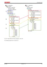
Страница 79: ...Commissioning EL922x 79 Version 1 0 Fig 67 EtherCAT terminal in the TwinCAT tree left TwinCAT 2 right TwinCAT 3...

Страница 80: ...online search is not available in RUN mode production operation Note the differentiation be tween TwinCAT programming system and TwinCAT target system The TwinCAT 2 icon or TwinCAT 3 icon within the W...

Страница 81: ...e respective devices are lo cated in the stored ESI data and integrated in the configuration tree in the default state defined there Fig 72 Example default state NOTE Slave scanning in practice in ser...

Страница 82: ...figuration B tsm in order to check the built machine However if the series machine production department now doesn t use B tsm but instead carries out a scan to create the productive configuration the...

Страница 83: ...hed to online state OPERATIONAL Fig 78 Config FreeRun query left TwinCAT 2 right TwinCAT 3 In Config FreeRun mode the System Manager display alternates between blue and red and the EtherCAT device con...

Страница 84: ...ce is detected i e an EtherCAT slave for which no ESI XML description is available In this case the System Manager offers to read any ESI that may be stored in the device This case is described in the...

Страница 85: ...guration is then replaced by the revision found this can affect the supported process data and functions If a scan is initiated for an existing configuration the actual I O environment may match the c...

Страница 86: ...sed on the higher revision number Device selection based on revision compatibility The ESI description also defines the process image the communication type between master and slave device and the dev...

Страница 87: ...offers a function Change to Compatible Type for the exchange of a device whilst retaining the links in the task Fig 87 Dialog Change to Compatible Type left TwinCAT 2 right TwinCAT 3 This function is...

Страница 88: ...s are now available for configuring the terminal And yet the dimension of complexity of a subscriber determines which tabs are provided Thus as illustrated in the example above the terminal EL3751 pro...

Страница 89: ...the start up phase Tick the control box to the left of the input field in order to modify the default value Previous Port Name and port of the EtherCAT device to which this device is connected If it...

Страница 90: ...difications include mask out a channel displaying additional cyclic information 16 bit display instead of 8 bit data size etc In so called intelligent EtherCAT devices the process data information is...

Страница 91: ...incorrect configuration the EtherCAT slave usu ally refuses to start and change to OP state The System Manager displays an invalid SM cfg log ger message This error message invalid SM IN cfg or invali...

Страница 92: ...t to the mailbox Move Up This button moves the selected request up by one position in the list Move Down This button moves the selected request down by one position in the list New This button adds a...

Страница 93: ...ct can be read but no data can be written to the object read only P An additional P identifies the object as a process data object Value Value of the object Update List The Update list button updates...

Страница 94: ...cts included in the object list of the slave is uploaded from the slave via SDO information The list below can be used to specify which object types are to be uploaded Offline via EDS File If this opt...

Страница 95: ...EtherCAT device Requested State Indicates the state requested for the EtherCAT device DLL Status Indicates the DLL status data link layer status of the individual ports of the EtherCAT slave The DLL...

Страница 96: ...ment of the selected Sync Manager All PDOs defined for this Sync Manager type are listed here If the output Sync Manager outputs is selected in the Sync Manager list all RxPDOs are displayed If the in...

Страница 97: ...eck box is selected the PDO assignment that is configured in the PDO Assignment list is downloaded to the device on startup The required commands to be sent to the device can be viewed in the Startup...

Страница 98: ...olour Meaning yellow Input variables from the Slave to the EtherCAT Master updated in every cycle red Output variables from the Slave to the EtherCAT Master updated in every cycle green Information va...

Страница 99: ...Commissioning EL922x 99 Version 1 0 Fig 101 Basic EtherCAT Slave Diagnosis in the PLC The following aspects are covered here...

Страница 100: ...y have effects on the process data of other Slaves that are located in the same Syn cUnit In order for the higher level PLC task or cor responding control applications to be able to rely on correct da...

Страница 101: ...ocally in the slave depends on the device EL terminals except the EL66xx are able to save in this way The user must manage the changes to the StartUp list Commissioning aid in the TwinCAT System Manag...

Страница 102: ...operation After the operating power is switched on an EtherCAT Slave must go through the following statuses INIT PREOP SAFEOP OP to ensure sound operation The EtherCAT Master directs these statuses i...

Страница 103: ...as standard EtherCAT Master OP Slaves OP This setting applies equally to all Slaves Fig 104 Default behaviour of the System Manager In addition the target state of any particular Slave can be set in...

Страница 104: ...e Fig 106 PLC function blocks Note regarding E Bus current EL ES terminals are placed on the DIN rail at a coupler on the terminal strand A Bus Coupler can supply the EL terminals added to it with the...

Страница 105: ...ove a warning message E Bus Power of Terminal is output in the logger window when such a configuration is activated Fig 108 Warning message for exceeding E Bus current NOTE Caution Malfunction possibl...

Страница 106: ...nt box underneath Restarting the EtherCAT system or reloading the configuration in configuration mode F4 causes the EtherCAT communication to restart and the process data is transferred from the termi...

Страница 107: ...taking these signals into account can it be ensured that all edges are taken into account This allows the user to leave a 1 for a signal edge change Reset or Switch until the associated input signal S...

Страница 108: ...yte bit 0x1A00 default OCP Inputs Channel 1 4 0 Status_Enabled Index 0x6000 01 124 0 1 Status_Tripped Index 0x6000 02 124 0 1 Offset 0 2 Status_Hardware Protection Index 0x6000 05 124 0 1 Offset 0 2 S...

Страница 109: ...t can it be ensured that all edges are taken into account This allows the user to leave a 1 for a signal edge change Reset or Switch until the associated input signal State Reset or State Switch refle...

Страница 110: ...AT system or reloading the configuration in configuration mode F4 causes the EtherCAT communication to restart and the process data is transferred from the terminal The following PDO assignments are p...

Страница 111: ...t 1 3 Load Index 0x6000 21 134 2 0 Current 0 01 A Index 0x6000 22 134 2 0 Voltage In 0 1 V Index 0x6000 23 134 2 0 Voltage Out 0 1 V Index 0x6000 24 134 2 0 0x1A01 default OCP Inputs Channel 2 12 0 St...

Страница 112: ...dex 0x6000 12 134 0 1 Status_Error Index 0x6000 13 134 0 1 Status_State Reset Index 0x6000 14 134 0 1 Status_State Switch Index 0x6000 15 134 0 1 Offset 1 3 0x1A03 OCP Inputs Channel 2 Compact 4 0 Sta...

Страница 113: ...for a signal edge change Reset or Switch until the associated input signal State Reset or State Switch reflects or acknowledges the 1 The same then occurs in the same way as the corresponding 0 signa...

Страница 114: ...ating the CoE parameters Keep a startup list if components have to be replaced Differentiation between online offline dictionary existence of current XML description use CoE reload for resetting chang...

Страница 115: ...tton programming option Indicated whether the nominal current of programmable terminals can be programmed via the LED button Disable Locked and not allowed Only one query of the nominal current is pos...

Страница 116: ...ominal Current Maximum nominal current UINT16 RW 800F 19 Nominal Current Type Nominal current adjustment option adjustable or fixed UINT16 RW 7 6 1 5 Input data Index 6000 Inputs Index hex Name Meanin...

Страница 117: ...available BOOLEAN RO 0x00 0dec 10F3 05 Flags not used UINT16 RW 0x0000 0dec 10F3 06 Diagnosis Message 001 Message 1 OCTET STRING 20 RO 0 10F3 15 Diagnosis Message 016 Message 16 OCTET STRING 20 RO 0...

Страница 118: ...01 1 PDO Mapping entry object 0x6000 Inputs Ch 1 entry 0x01 Enabled UINT32 RO 0x6000 01 1 1A00 02 SubIndex 002 2 PDO Mapping entry object 0x6000 Inputs Ch 1 entry 0x02 Tripped UINT32 RO 0x6000 02 1 1A...

Страница 119: ...ts UINT8 RO 0x03 3dec 1C00 04 SubIndex 004 Sync Manager Type Channel 4 Process Data Read Inputs UINT8 RO 0x04 4dec Index 1C12 RxPDO assign Index hex Name Meaning Data type Flags Default 1C12 0 RxPDO a...

Страница 120: ...rement through writing of 0x1C33 08 UINT16 RO 0x8001 32769dec 1C33 05 Minimum cycle time Minimum cycle time in ns UINT32 RO 0x00002710 10000dec 1C33 06 Calc and copy time Time between reading of the i...

Страница 121: ...3 DC Mode Synchron with SYNC1 Event UINT16 RW 0x0001 1dec 1C32 02 Cycle time Cycle time in ns Free Run Cycle time of the local timer Synchron with SM 2 Event Master cycle time DC mode SYNC0 SYNC1 Cyc...

Страница 122: ...UINT16 RO 0x0000 0dec 1C32 14 Frame repeat time UINT32 RW 0x00000000 0dec 1C32 20 Sync error The synchronization was not correct in the last cycle outputs were output too late DC mode only BOOLEAN RO...

Страница 123: ...ion Indicated whether the nominal current of programmable terminals can be programmed via the LED button Disable Locked and not allowed Only one query of the nominal current is possible Enable Program...

Страница 124: ...ominal Current Maximum nominal current UINT16 RW 80nF 19 Nominal Current Type Nominal current adjustment option adjustable or fixed UINT16 RW 7 6 2 5 Input data Index 60n0 Inputs for n 0 Ch 1 n 1 Ch 2...

Страница 125: ...essage is available BOOLEAN RO 0x00 0dec 10F3 05 Flags not used UINT16 RW 0x0000 0dec 10F3 06 Diagnosis Message 001 Message 1 OCTET STRING 20 RO 0 10F3 15 Diagnosis Message 016 Message 16 OCTET STRING...

Страница 126: ...SubIndex 001 1 PDO Mapping entry object 0x6000 Inputs Ch 1 entry 0x01 Enabled UINT32 RO 0x60n0 01 1 1A0n 02 SubIndex 002 2 PDO Mapping entry object 0x6000 Inputs Ch 1 entry 0x02 Tripped UINT32 RO 0x6...

Страница 127: ...12 RxPDO assign Index hex Name Meaning Data type Flags Default 1C12 0 RxPDO assign PDO Assign Outputs UINT8 RO 0x02 2dec 1C12 01 Subindex 001 1 allocated RxPDO contains the index of the associ ated Rx...

Страница 128: ...rement through writing of 0x1C33 08 UINT16 RO 0x8001 32769dec 1C33 05 Minimum cycle time Minimum cycle time in ns UINT32 RO 0x00002710 10000dec 1C33 06 Calc and copy time Time between reading of the i...

Страница 129: ...SYNC0 Event 3 DC Mode Synchron with SYNC1 Event UINT16 RW 0x0001 1dec 1C32 02 Cycle time Cycle time in ns Free Run Cycle time of the local timer Synchron with SM 2 Event Master cycle time DC mode SYNC...

Страница 130: ...ame repeat time UINT32 RW 0x00000000 0dec 1C32 20 Sync error The synchronization was not correct in the last cycle outputs were output too late DC mode only BOOLEAN RO 0x00 0dec Index F009 Password pr...

Страница 131: ...xecuted if required It de scribes the behavior so to speak Reset only power on off only reset and power on off or disabled UINT8 RW 0x02 2dec 80n0 16 Overvoltage Behav iour Overvoltage behavior Descri...

Страница 132: ...triggering oc curs at 2 4 times IN UINT16 RW 0x0000 0dec 80n1 0D Time value 2 6 In Describes the tripping time in ms when triggering oc curs at 2 6 times IN UINT16 RW 0x0000 0dec 80n1 0E Time value 2...

Страница 133: ...type Flags Default value 80n1 0 DIG Safe State Value Maximum subindex UINT8 RO 0x01 1dec 80n1 01 Value Defines the state of the output in case of a bus error 0 output off 1 output on BOOLEAN RW 0x00 0...

Страница 134: ...us__Hardware Protection Hardware protection for overtemperature reverse feed wiring error and redundant current measure ment is displayed as long as the state is active BOOLEAN RO 0x00 0dec 60n0 06 St...

Страница 135: ...used UINT16 RW 0x0000 0dec 10F3 06 Diagnosis Message 001 Message 1 OCTET STRING 20 RO 0 10F3 15 Diagnosis Message 016 Message 16 OCTET STRING 20 RO 0 Index 10F8 Actual Time Stamp Index hex Name Meani...

Страница 136: ...ipping time in ms when triggering oc curs at 2 4 times IN UINT16 RO 0x0000 0dec 90n1 0D Time value 2 6 In Describes the tripping time in ms when triggering oc curs at 2 6 times IN UINT16 RO 0x0000 0de...

Страница 137: ...Operation mode EtherCAT stand alone UINT8 RO 0x00 0dec 90n3 12 Password Protection Password protection UINT8 RO 0x00 0dec 90n3 13 Timestamp Type Type of timestamp relative or absolute UINT8 RO 0x00 0...

Страница 138: ...32 RO 0x00000002 2dec 1018 02 Product code Product code of the EtherCAT slave UINT32 RO 0x240B3052 604713042dec 1018 03 Revision Revision number of the EtherCAT slave the low word bit 0 15 indicates t...

Страница 139: ...ag UINT32 RO 0x6000 0D 1 1A00 0E SubIndex 014 14 PDO Mapping entry object 0x6000 Inputs Ch 1 entry 0x0E TxPDO State UINT32 RO 0x6000 0E 1 1A00 0F SubIndex 015 15 PDO Mapping entry object 0x6000 Inputs...

Страница 140: ...02 Subindex 002 2 allocated RxPDO contains the index of the associ ated RxPDO mapping object UINT16 RO 0x1601 5633dec Index 1C13 TxPDO assign Index hex Name Meaning Data type Flags Default 1C13 0 TxP...

Страница 141: ...rement through writing of 0x1C33 08 UINT16 RO 0x8001 32769dec 1C33 05 Minimum cycle time Minimum cycle time in ns UINT32 RO 0x00002710 10000dec 1C33 06 Calc and copy time Time between reading of the i...

Страница 142: ...UINT16 RW 0x0001 1dec 1C32 02 Cycle time Cycle time in ns Free Run Cycle time of the local timer Synchron with SM 2 Event Master cycle time DC mode SYNC0 SYNC1 Cycle Time UINT32 RW 0x000F4240 1000000...

Страница 143: ...ing Data type Flags Default F009 0 Password protection Password protection UINT32 RW 0x00000000 0dec Index 1800 OCP TxPDO Par Inputs Ch 1 Index hex Name Meaning Data type Flags Default 1800 0 OCP TxPD...

Страница 144: ...UINT16 RO 0x0010 16dec F000 02 Maximum number of modules Number of channels UINT16 RO 0x0002 2dec Index F010 Module list Index hex Name Meaning Data type Flags Default F010 0 Module list Max Subindex...

Страница 145: ...x09 Cool Down Lock UINT32 RO 0x6000 09 1 1A01 0A SubIndex 010 10 PDO Mapping entry object 0x6000 Inputs Ch 1 entry 0x0A Disabled By Switch UINT32 RO 0x6000 0A 1 1A01 0B SubIndex 011 11 PDO Mapping ent...

Страница 146: ...ntry 0x0B Disabled By DI UINT32 RO 0x6010 0B 1 1A02 0C SubIndex 012 12 PDO Mapping entry object 0x6010 Inputs Ch 2 entry 0x0C Disabled By Output UINT32 RO 0x6010 0C 1 1A02 0D SubIndex 013 13 PDO Mappi...

Страница 147: ...0 10 PDO Mapping entry object 0x6010 Inputs Ch 2 entry 0x0A Disabled By Switch UINT32 RO 0x6010 0A 1 1A03 0B SubIndex 011 11 PDO Mapping entry object 0x6010 Inputs Ch 2 entry 0x0B Disabled By DI UINT3...

Страница 148: ...are can store up to 250 DiagMessages in its own CoE Each DiagMessage consists of Diag Code 4 byte Flags 2 byte info warning or error Text ID 2 byte reference to explanatory text from the ESI XML Times...

Страница 149: ...tlogger Since TwinCAT 3 1 build 4022 DiagMessages send by the terminal are shown by the TwinCAT ADS Logger Given that DiagMessages are represented IO comprehensive at one place commissioning will be s...

Страница 150: ...and can be supplier specifically defined In the case of Beckhoff EtherCAT devices EL EP it usually reads according to xyzz x y zz 0 Systeminfo 2 reserved 1 Info 4 Warning 8 Error 0 System 1 General 2...

Страница 151: ...General internal hardware error error code error code 11 missing input voltage channel 1 12 missing input voltage channel 2 21 faulty redundant current measurement channel 1 22 faulty redundant curren...

Страница 152: ...the separate page 154 If a device is placed in BOOTSTRAP mode for a firmware update it does not check when downloading whether the new firmware is suitable This can result in damage to the device Ther...

Страница 153: ...9222 9664 0016 20xx xx EL9227 4433 Hardware HW Firmware Revision no Release date 00 01 01 EL9227 4433 0016 20xx xx EL9227 5500 Hardware HW Firmware Revision no Release date 00 01 01 EL9227 5500 0016 2...

Страница 154: ...his purpose Generally the slave does not check whether the new data are suitable i e it may no longer be able to operate if the data are unsuitable Simplified update by bundle firmware The update usin...

Страница 155: ...vision 0016 The configured identifier must be compatible with the actual device description used as hardware i e the description which the slave has loaded on start up in this case EL3204 Normally the...

Страница 156: ...uration is identical otherwise a change dialog appears for entering the actual data in the configuration Fig 114 Change dialog In this example in Fig Change dialog an EL3201 0000 0017 was found while...

Страница 157: ...d in the following dialog see Fig Selecting the new ESI The checkbox Show Hidden Devices also displays older normally hidden versions of a slave Fig 116 Selecting the new ESI A progress bar in the Sys...

Страница 158: ...terminal 2 EL3204 and select the tab CoE Online CAN over EtherCAT CoE Online and Offline CoE Two CoE directories are available online This is offered in the EtherCAT slave by the controller if the Eth...

Страница 159: ...ated EEPROM which is generally not changed during a firmware update Switch to the Online tab to update the controller firmware of a slave see Fig Firmware Update Fig 118 Firmware Update Proceed as fol...

Страница 160: ...date may be accomplished via an rbf file Controller firmware for processing I O signals FPGA firmware for EtherCAT communication only for terminals with FPGA The firmware version number included in th...

Страница 161: ...right click the table header and select Properties in the context menu Fig 120 Context menu Properties The Advanced Settings dialog appears where the columns to be displayed can be selected Under Dia...

Страница 162: ...terminal must have FPGA firmware version 10 or higher Older firmware versions can only be updated by the manufacturer Updating an EtherCAT device The following sequence order have to be met if no othe...

Страница 163: ...nager select the terminal for which the FPGA firmware is to be updated in the example Terminal 5 EL5001 and click the Advanced Settings button in the EtherCAT tab The Advanced Settings dialog appears...

Страница 164: ...the device A download of firmware to an EtherCAT device must not be interrupted in any case If you interrupt this process by switching off power supply or disconnecting the Ethernet link the EtherCAT...

Страница 165: ...PDO Double click on SubIndex 001 to enter the Set Value dialog Enter the value 1684107116 in field Dec or the value 0x64616F6C in field Hex and confirm with OK Fig Entering a restore value in the Set...

Страница 166: ...0 Alternative procedure Alternatively the factory settings can be restored by simultaneously pressing the two buttons in pro gramming mode for more than 5 seconds This alternative procedure is only av...

Страница 167: ...nents there Beckhoff Headquarters Beckhoff Automation GmbH Co KG Huelshorstweg 20 33415 Verl Germany Phone 49 0 5246 963 0 Fax 49 0 5246 963 198 e mail info beckhoff com Beckhoff Support Support offer...

Страница 168: ...Machine 25 Fig 16 CoE Online tab 27 Fig 17 Startup list in the TwinCAT System Manager 28 Fig 18 Offline list 29 Fig 19 Online list 29 Fig 20 Spring contacts of the Beckhoff I O components 31 Fig 21 At...

Страница 169: ...es left TwinCAT 2 right TwinCAT 3 76 Fig 63 Selection dialog for new EtherCAT device 77 Fig 64 Display of device revision 77 Fig 65 Display of previous revisions 78 Fig 66 Name revision of the termina...

Страница 170: ...haviour of the System Manager 103 Fig 105 Default target state in the Slave 103 Fig 106 PLC function blocks 104 Fig 107 Illegally exceeding the E Bus current 105 Fig 108 Warning message for exceeding...

Отзывы: