8.13.2
SSI output (X5)
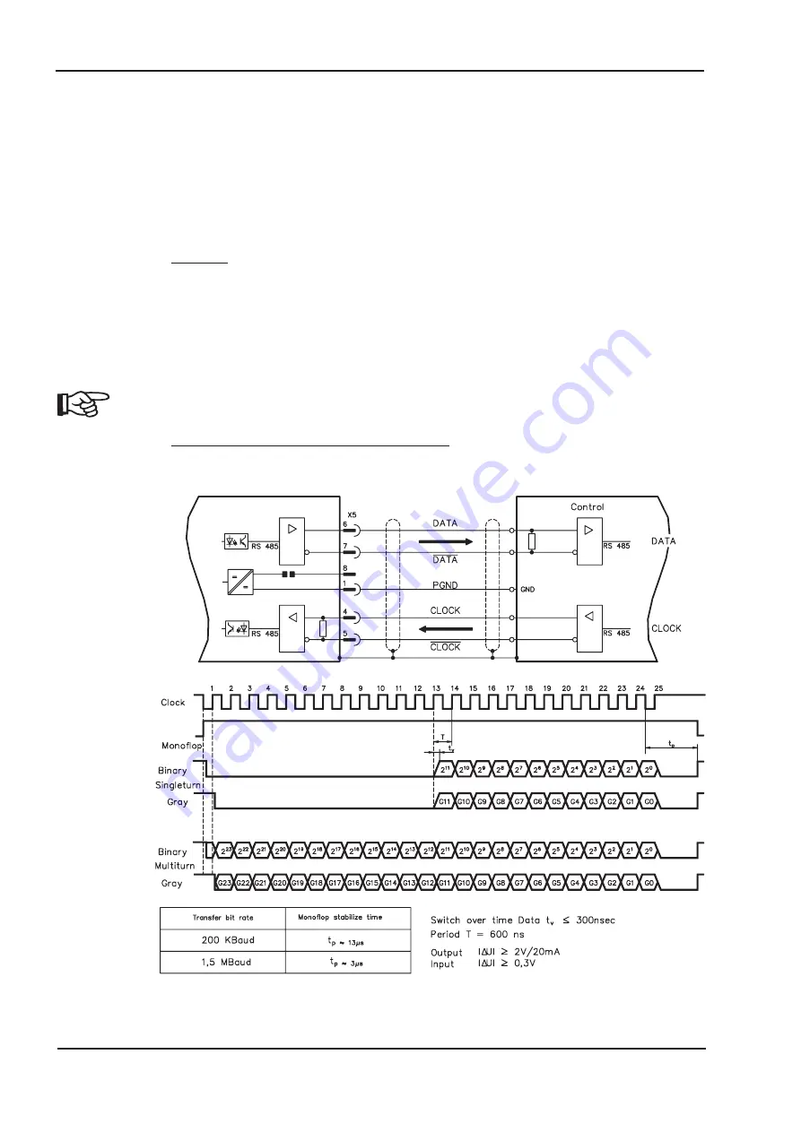
The SSI interface (synchronous serial absolute-encoder simulation) is part of the delivered
package. Select the encoder function SSI (screen page “Encoder”). In the servo amplifier, the posi-
tion of the motor shaft is calculated from the cyclically absolute signals from the resolver or encoder.
This information is used to create a position output in a format that is compatible with the standard
SSI-absolute-encoder format. 24 bits are transmitted.
SINGLE TURN selected
: The upper 12 bits are fixed to ZERO, the lower 12 bits contain the posi-
tion information. For 2-pole resolvers, the position value refers to the position within one turn of the
motor, for 4-pole resolvers it is within half a turn, and for 6-pole resolvers it is within a third of a turn.
Exception: If an encoder with a commutation track is used as the feedback unit, then the upper 12
bits are set to 1 (data invalid!) until a homing run is performed.
MULTI TURN selected
: The upper 12 bits contain the number of motor turns, the lower 12 bits con-
tain the position information.
The signal sequence can be output in
Gray
code (standard) or in
binary
code (parameter
SSI-CODE). The servo amplifier can be adjusted to the clock frequency of your SSI-evaluation with
the SSI-CLOCK parameter (cycle time 200 kHz or 1.5 MHz and inverted).
The drivers are supplied from internal supply voltage. PGND must always be
connected.
Connection and signal description for SSI interface :
The count direction is upwards when the motor shaft is rotating clockwise (looking at the shaft end).
62
AX2040/2070 Product Manual
Electrical Installation
06/2007
BECKHOFF
AX2040/2070
Содержание AX2040
Страница 35: ...7 4 Dimensions AX2040 2070 Product Manual 35 BECKHOFF 06 2007 Mechanical Installation...
Страница 44: ...8 6 Pin assignments 44 AX2040 2070 Product Manual Electrical Installation 06 2007 BECKHOFF...
Страница 108: ...This page has been deliberately left blank 108 AX2040 2070 Product Manual Expansion Cards 06 2007 BECKHOFF...


