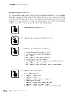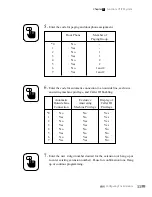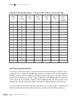
18
RS232 Pin-out Diagram For Printer Connection
Pin Function
1 No
Connection
2
Data out of IPS
3
Data into IPS
4
Data Terminal Ready (Connected to Pin 6 on IPS)
5 Ground
6
Data Set Ready (Connected to Pin 4 on IPS)
7
Request to Send (Connected to Pin 8 on IPS)
8
Clear to Send (Connected to Pin 7 on IPS)
9 No
Connection
Checking The System For Proper Operation
After all the necessary extension wiring is properly connected, replace the phone jack access
panel and fasten it using the retaining screw. Plug the IPS unit in the A.C. outlet.
Test each extension
1. Plug a single line telephone into the RJ-11 connector at the extension location and listen to the
system dial tone.
2. Call another extension and listen for a ring.
3. Dial “9”, then listen for an outside dial tone.
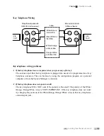
If a dial tone is not heard and/or dialing cannot be performed, check the wiring at the jack for that
extension. For all extensions except those connected to key telephones, use only a 2-wire and not
a 4-wire connection. Do not connect the second pair. Some older telephones may use the outer
two wires which can disrupt the operation of the phones or disrupt the operation of key telephones
at other extensions. If the connection is good, it is possible that the telephone you are using is
polarity sensitive. Please reverse the wiring at the terminal block for the problem extension. A dial
tone should now be heard and you should be able to dial.
Installing Your Phone System Unit
Chapter
2
- Installation Guide
Содержание IPS 308
Страница 8: ...1 Introduction Chapter 1 Of IPS System...
Страница 11: ...5 Installation Chapter 2 Guide...
Страница 28: ...23 Functions Of Chapter 3 IPS System...
Страница 107: ...103 IPS System Used With Chapter 4 Ordinary Telephones...
Страница 132: ...129 IPS System Used With Chapter 5 IVT 16 Key Telephone...


