


Manual 2100-620A
Page
57 of 107
COMPONENTRY SPECIFICATIONS
LOW PRESSURE SWITCH
Cut-out pressure: 40psi (+/- 4 psi)
Cut-in pressure: 55psi (+/- 4psi)
HIGH PRESSURE SWITCH
Cut-out pressure: 650psi (+/- 10 psi)
Cut-in pressure: 520psi (+/- 15psi)
LOW AMBIENT CONTROL
Modulating head-pressure control that allows full
speed at pressures above 315psi. Below 315psi, the
control will slow fan speed—following internal head
pressures—until a minimum RPM is reached (approx
300 RPM). Below this point, the control will shut the
fan completely off until internal pressures rise. The
control is preset from the factory, but should adjustment
become necessary, there is an adjustment screw located
on the bottom of the control behind a weatherproof cap.
One full turn clockwise equals approxi48 psi.
REMOTE INDOOR TEMPERATURE
SENSOR
White, decorative plastic casing, Bard logo, field-
installed in shelter: 10k ohm resistance, see Table 2.5
on page 58.
DISCHARGE TEMP SENSOR
4.75” stainless probe factory mounted in supply
opening of wall-mount unit: 10k ohm resistance, see
Table 2.5 on page 58.
RETURN TEMPERATURE SENSOR
Exposed thermistor-element style with copper-coated
steel clip, attached in return opening of wall-mount
unit: 10k ohm resistance, see Table 2.5 on page 58.
EVAPORATOR TEMP SENSOR
(FREEZESTAT)
Exposed thermistor-element style with copper-coated
steel clip, attached to evaporator coil of wall-mount unit:
10k ohm resistance, see Table Table 2.5 on page 58.
OUTDOOR TEMPERATURE/HUMIDITY
SENSOR
Gray, weather-proof octagonal case with dip tube,
located in condenser section of wall-mount unit.
• Temperature sensor: 10k ohm resistance, see Table
2.5 on page 58.
• Humidity sensor: 4-20mA.
COMPRESSOR CONTROL MODULE
Compressor protection device that has an adjustable
30-second to 5-minute timer (red-dial). This module
features a delay-on make for initial start-up (or anytime
power is interrupted) for a minum 2 minutes plus 10%
of the red-dial setting. There is no delay during routine
operation of the unit. The compressor control module
(CCM) also monitors the high pressure switch, and
will allow one automatic retry (after soft lockout delay)
before disabling the compressor in a hard lockout
(requires manual reset). If hard lockout does occur,
the ALR terminal on the CCM will become active with
24V, which will power the high pressure relay within
the wall-mount unit, breaking a digital input to the
PLC control—signaling a high-pressure situation to the
system.
PHASE MONITOR
Used only on 3-phase equipment, the phase
monitor is a compressor protection device that will
prohibit operation of the compressor if the device
senses a possible reverse-rotation situation due to
incorrect phasing. On a call for compressor (and only
compressor), the device will check incoming phase,
check for severe voltage imbalance and check for
proper frequency. Under nominal conditions, a green
LED light will show on the face of the monitor. If there
is improper phasing, voltage imbalance or frequency
deviation, the device will show a red LED light and
prohibit compressor operation.
TRANSFORMER
75VA with external 4A circuit breaker, 230VAC/208VAC
convertible. Directly feeds power loss relay in wall-
mount unit during normal operation. Should loss of
utility power occur, transformer failure or transformer
external circuit breaker open, the loss of VAC power
will cause the contacts within the power loss relay to
open, interrupting a digital input to the PLC control—
signaling a loss-of-power situation to the system.
FUSED TERMINAL BLOCKS
Black, hinged DIN-rail mount terminal block with
an internal glass tube fuse, used in the LC-Series
controller for 24VDC power supply to both hydrogen
and smoke alarms: Phoenix UK5-HESI
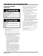
Electrical shock hazard.
Disconnect both VAC and VDC power supplies
before servicing.
Failure to do so could result in electric shock
or death.
!
WARNING
Содержание D36A2P/BLD.10304
Страница 6: ...Manual 2100 620A Page 6 of 107 ...
Страница 7: ...Manual 2100 620A Page 7 of 107 SECTION 1 INSTALLATION INSTRUCTIONS ...
Страница 39: ...Manual 2100 620A Page 39 of 107 SECTION 2 SERVICE INSTRUCTIONS ...
Страница 73: ...Manual 2100 620A Page 73 of 107 SECTION 3 PARTS MANUAL ...
Страница 88: ...Manual 2100 620A Page 88 of 107 BARD LINKTM PLC LEAD LAG CONTROLLER SEXP 755 6 4 8 7 2 9 1 5 3 ...
Страница 90: ...Manual 2100 620A Page 90 of 107 ...
Страница 91: ...Manual 2100 620A Page 91 of 107 SECTION 4 APPENDICES ...


