


Manual 2100-620A
Page
46 of 107
send digital inputs to the board as well as open
contacts 19 and 20. The LC board will then send
remote alarms and direct both wall-mount units to
activate free cooling dampers to dilute the shelter
with outdoor air until cleared.
• Generator Run: If there is a generator onsite that
is not large enough to power both wall-mount units
in mechanical cooling, the installers were to pull
a factory-installed jumper on terminals 9 and 10
and wire those terminals to the normally closed
contacts of an existing or field-provided generator
run relay. If this has been done, when the
generator activates, the existing or field-provided
generator run relay will open contacts and sever
the -24VDC to terminal 10. This will de-energize
the internal generator run relay, which will send
digital inputs to the board as well as open contacts
on terminals 21 and 22. The LC board will then
send remote alarms and direct only the LEAD unit
to operate until cleared. If the factory-mounted
jumper has not been removed, generator operation
will have no effect on the controller actions.
• Low Temp: If 45°F is sensed in the shelter, the LC
board will send -24VAC to the low temp relay to
energize the relay, opening contacts on terminals
27 and 28. Additionally, the board will send
remote alarms.
• High Temp: If 90°F is sensed in the shelter, the LC
board will send -24VAC to the high temp relay to
energize the relay, opening contacts on terminals
25 and 26. Additionally, the LC will send remote
alarms and enable blowers and free cooling
dampers in an attempt to cool the shelter.
• HVAC 1 Fail: The HVAC 1 fail relay will be
energized from the LC board through any of the
following situations:
-
Unit 1 Loss of Power
-
Unit 1 Dirty Filter Switch
-
Unit 1 High/Low Pressure Switches
-
Unit 1 SAT/OAT/RAT/OAH Sensor Fail
-
Unit 1 Loss of Communication
-
Unit 1 Damper Fail to Open/Close
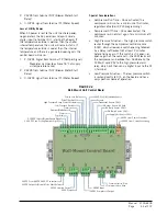
FIGURE 2.4
LC Series Controller Control Board
–24VDC from Converter
–24VDC to High Temp Isolation Relay
–24VDC to Low Temp Isolation Relay
–24VDC to HVAC 1 Fail Isolation Relay
HVAC 2 Fail Run Contact T31
HVAC 2 Fail Run Common T32
DI Common for Smoke, Hydrogen and
Gen Run Isolation Relays
Gen Run ALR Isolation Relay DI
Hydrogen ALR Isolation Relay DI
Smoke ALR Isolation Relay DI
Sensor Common T12, T14, T16
+24VDC
T11 Indoor Temp Sensor 10kOhm
–24VDC
T13 Optional 2
nd
Indoor Temp Sensor 10kOhm
T15 Optional 2
nd
Indoor Temp Sensor 10kOhm
T24 Lag Unit Run Contact
T23 Lag Unit Run Common
+ Communication Wire
– Communication Wire
LC-Series Control Board
Содержание D36A2P/BLD.10304
Страница 6: ...Manual 2100 620A Page 6 of 107 ...
Страница 7: ...Manual 2100 620A Page 7 of 107 SECTION 1 INSTALLATION INSTRUCTIONS ...
Страница 39: ...Manual 2100 620A Page 39 of 107 SECTION 2 SERVICE INSTRUCTIONS ...
Страница 73: ...Manual 2100 620A Page 73 of 107 SECTION 3 PARTS MANUAL ...
Страница 88: ...Manual 2100 620A Page 88 of 107 BARD LINKTM PLC LEAD LAG CONTROLLER SEXP 755 6 4 8 7 2 9 1 5 3 ...
Страница 90: ...Manual 2100 620A Page 90 of 107 ...
Страница 91: ...Manual 2100 620A Page 91 of 107 SECTION 4 APPENDICES ...


