


Manual 2100-620A
Page
45 of 107
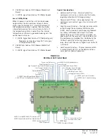
NC Contacts for External Alarm(s):
• Smoke alarm NC contacts on terminals 17 and 18.
• Hydrogen alarm NC Contacts on terminals 19 and
20.
• Generator run alarm NC contacts on terminals 21
and 22.
• Lag unit run alarm NC contacts on terminals 23
and 24.
• High temp fail alarm NC contacts on terminals 25
and 26.
• Low temp fail alarm NC contacts on terminals 27
and 28.
• HVAC 1 contacts on terminals 29 and 30.
• HVAC 2 contacts on terminals 31 and 32.
Communication Output:
• Negative (-) communication wire to terminal 33.
• Positive (+) communication wire to terminal 34.
• Cable drain wire to terminal 35.
Isolation Relays and Alarm Schemes
Note that three of the factory-wired isolation relays
(smoke, hydrogen and generator) will be always
energized by their respective detectors
—with all alarm
signals sent through the NO contacts of the relays
(which are closed as long as the relays are energized).
The remaining three factory-wired isolation relays
(low temp, high temp and HVAC 1 fail) relays are only
energized during an alarm situation, and all alarm
signals are sent through the NC contacts of the relays.
These contacts open on alarm.
• Smoke: If smoke is detected in the shelter, the
detector will open internal contact supplying
-24VDC to terminal 8. This will de-energize the
smoke isolation relay, which will send digital inputs
to the board as well as open contacts 17 and 18.
Board will then send remote alarms, and direct
both wall-mount units to cease all operations until
cleared.
• Hydrogen (if installed): If hydrogen is detected in
the shelter, the detector will open internal contact
supplying -24VDC to terminal 5. This will de-
energize the hydrogen isolation relay, which will
FIGURE 2.3
LC Series Controller Control Board and Terminal Block
Содержание D36A2P/BLD.10304
Страница 6: ...Manual 2100 620A Page 6 of 107 ...
Страница 7: ...Manual 2100 620A Page 7 of 107 SECTION 1 INSTALLATION INSTRUCTIONS ...
Страница 39: ...Manual 2100 620A Page 39 of 107 SECTION 2 SERVICE INSTRUCTIONS ...
Страница 73: ...Manual 2100 620A Page 73 of 107 SECTION 3 PARTS MANUAL ...
Страница 88: ...Manual 2100 620A Page 88 of 107 BARD LINKTM PLC LEAD LAG CONTROLLER SEXP 755 6 4 8 7 2 9 1 5 3 ...
Страница 90: ...Manual 2100 620A Page 90 of 107 ...
Страница 91: ...Manual 2100 620A Page 91 of 107 SECTION 4 APPENDICES ...


