5
Built-in Trim Kit Installation:
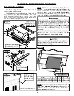
Prior to installing unit, side and rear trims must be
installed to fully support the unit.
Carefully remove the stainless steel trim pieces from the
carton and attach Left, Right & Rear stainless trims to left,
right & rear sides of barbecue using 10 bolts & 2 nuts. Check
to make sure they are aligned flush with the side barbecue
face and top before fully tightening the bolts.
NOTE:
When choosing a location for your Gas grill, keep in
mind that it should not be located under any overhead com-
bustible construction. The
side and bottom
of the grill
should not be any closer than
14 inches to combustible
construction
, and the
back
of the grill should not be any
closer than
16 inches to combustible construction.
n
WARNING
Failure to comply with these instructions could result in a
fire or explosion that could cause serious bodily injury,
death, or property damage.
Figure 3
1/4”-20 x 1/2” Phillips
Head Screw (12 ea.)
3/16” x 1/4”
Phillips Head
Screw (2 ea.)
1/4” Flange Nut
(4 ea.)
Figure 4
3/16” x 1/4”
Phillips Head
Screw (2 ea.)
Figure 5
Rear view of barbecue
Outdoor BBQ Built-in Installation Specifications
C
B
D
E
A
Model
A
B
C
D
E
GE3BSSLP/NG 10-1/4" 28-3/4" 23"
14"
16"
GE4BSSLP/NG 10-1/4" 36-5/8" 23"
14"
16"
non-combustible
construction
Figure 6
n
WARNING
Vapors from products containing Chlorine and other caus-
tic chemicals can cause Stainless Steel flexible connectors
to corrode. THESE PRODUCTS SHOULD NOT BE
STORED IN AN ISLAND OR NEAR THE connector.
Cleaning solutions, Household Chemicals and Solder flux-
es can also cause pinholes if they come in contact with
these connectors and
MUST
be washed off immediately
with water.
NOTE:
Upper & lower ground-level vents (20 sq. in. mini-
mum each)
MUST BE PROVIDED
for combustion air on
both sides of built-in construction. Please ask a Barbeques
Galore associate for full details.
Barbecues must be installed in accordance with CSA
specifications and all local building codes.
Содержание Grand Endevator GE3BSSLP
Страница 2: ......
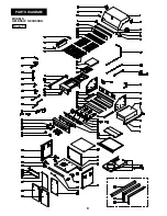
Страница 9: ...8 PARTS DIAGRAM MODELS GE3BSSLP GE3BSSNG Figure 13 ...
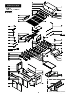
Страница 10: ...9 PARTS DIAGRAM MODELS GE4BSSLP GE4BSSNG Figure 14 ...

