16
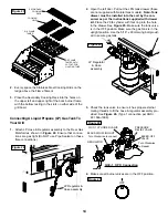
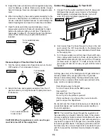
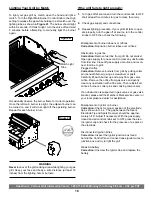
Side Burner Connection
1.
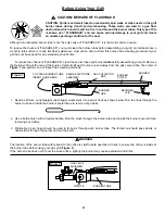
Install the Side Burner Connection Hose into Socket as
shown in
Figures 32 & 33
.
2.
To connect, push back Socket Sleeve, insert Plug then
release Sleeve (
Figure 33
). Push plug until sleeve
snaps forward, locking the Plug into the socket.
Checking For LP Gas Leaks
Never
test for leaks with a flame. Prior to first use, at the
beginning of each season, or every time your LP gas tank
is changed, you must check for gas leaks. Follow these
four steps:
1.
Make a soap solution by mixing one part liquid deter-
gent and one part water.
2.
Turn the grill control knobs to the full OFF position, then
turn the gas ON at source.
3.
Apply the soap solution to all gas connections. If bub-
bles appear in the soap solution the connections are
not properly sealed. Check each fitting and tighten or
repair as necessary.
4.
If you have a gas leak that you cannot repair, turn off
the gas at the source, disconnect fuel line from your
grill and call 1-800-
752-3085
or your gas supplier for
repair assistance.
Grill Lighting Instructions
Basic Lighting Procedures
1.
Familiarize yourself with the safety guidelines at the front
of this manual. Do not smoke while lighting grill or check-
ing gas supply connections.
2.
Be sure the LP gas tank is filled.
3.
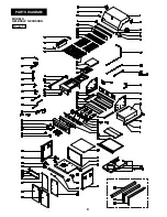
Check that the end of each burner tube is properly locat-
ed over each valve orifice.
4.
Make sure all gas connections are securely tightened.
5.
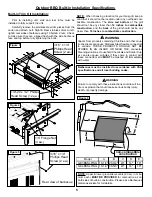
Open the Grill Lid or Side Burner Lid, depending on the
burner you are lighting.
n
WARNING
Failure to open Grill Lid during the lighting procedures
could result in a fire or explosion that could cause seri-
ous bodily injury, death, or property damage.
6.
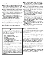
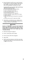
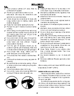
Set control knobs to OFF and open the LP gas tank
valve slowly until 1/4 to 1/2 open.
Figure 32
Side Burner
Connection
Hose
Figure 33
Socket
Sleeve
Plug
Pull back Sleeve
and insert Plug
Release Sleeve so that it
snaps & locks in place
Turn counterclockwise
to open
OFF
Figure 34
Turn counterclockwise
to open
OFF
Figure 35
Содержание Grand Endevator GE3BSSLP
Страница 2: ......
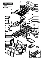
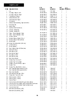
Страница 9: ...8 PARTS DIAGRAM MODELS GE3BSSLP GE3BSSNG Figure 13 ...
Страница 10: ...9 PARTS DIAGRAM MODELS GE4BSSLP GE4BSSNG Figure 14 ...


