SureCross™ DX80 Quick Start Guide
A setup guide for the SureCross™ DX80 wireless systems
Printed in USA
02/07
P/N 128185 Rev A
Introducing the SureCross™ DX80 Wireless System
The SureCross™ DX80 wireless system provides reliable monitoring
without the burden of wiring or conduit installation, and can operate
independently or in conjunction with a PLC and/or PC software.
The SureCross DX80 network is a deterministic system - the network
identi
fi
es when the radio signal is lost and drives relevant outputs
to user-de
fi
ned conditions. Once the radio signal is reacquired, the
network returns to normal operation.
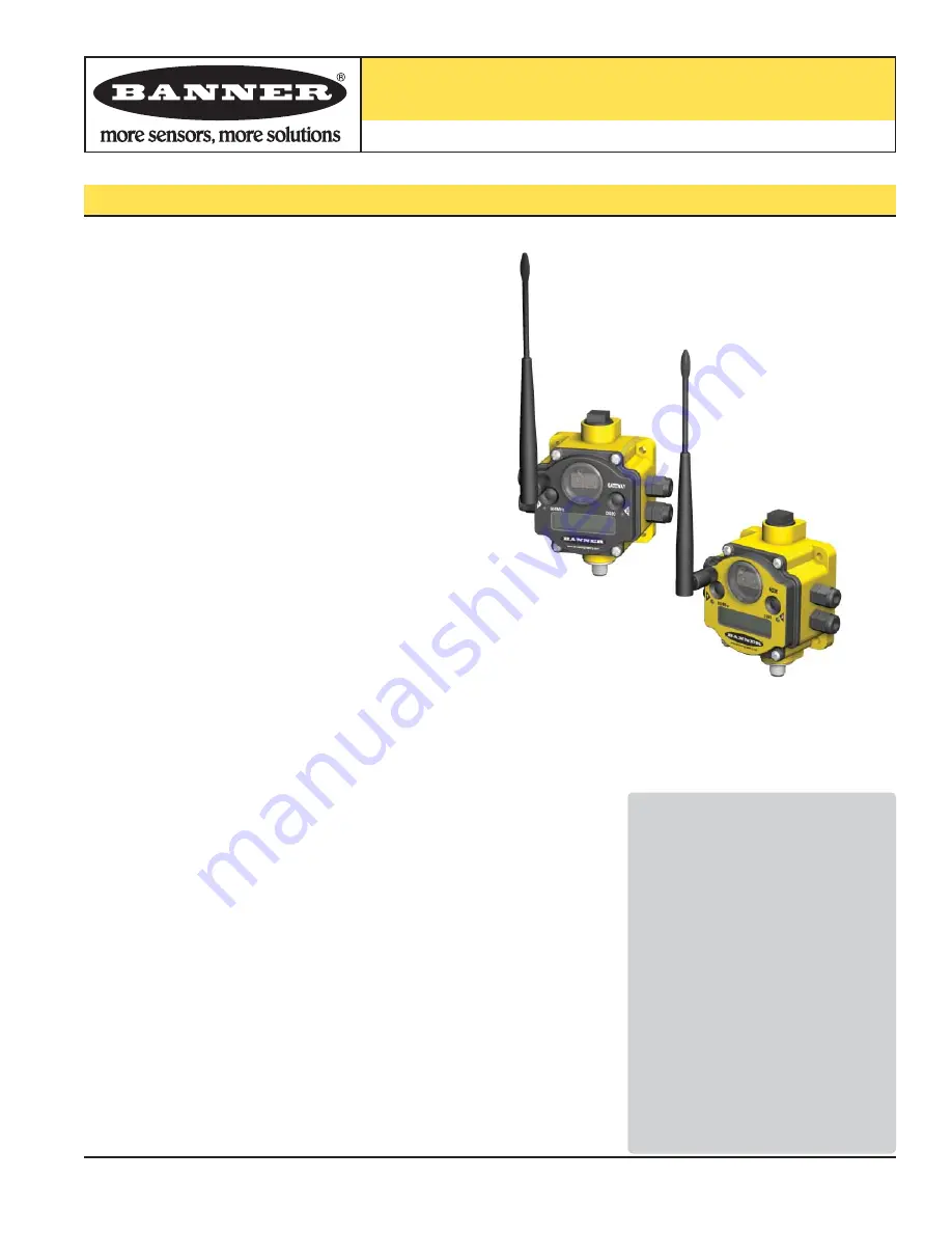
Each wireless system consists of one Gateway and one or more
Nodes that ship with factory prede
fi
ned inputs and outputs.
Devices may be all discrete I/O, mixed discrete and analog I/O, and
Flex
Power™.
A Gateway device acts as the master device within each radio network
system. The Gateway initiates communication and reporting with the
Nodes.
A radio network contains only one Gateway, but can contain many
Nodes. Each Node device can be connected to a sensor or output
device and reports I/O status to the Gateway.
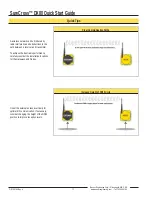
A Gateway and Node can be arranged to extend the range of the
network or to avoid obstacles in the transmission path. The Gateway
receives a transmission from one Node and forwards it to another
Node positioned to avoid the obstacle.
Host-connected systems can contain up to 15 nodes within a single
network and may be all discrete or a mix of discrete and analog I/O.
Host-connected systems allow for logic and calculations to be applied
to the I/O. Inputs from Nodes within the network are transmitted to the
Gateway, which communicates the information to a host device for
processing. While the Gateway is the master device within the radio
network, the Gateway is a slave to the Modbus network.
Flex
Power devices allow for a true wireless solution as the Node can
be powered by line power (10 to 30V dc) or battery power (3.6 to 5.5V
dc). A SureCross DX81 battery pack and unique power management
system runs the Node and a device for up to
fi
ve years, depending
upon the power requirements of the device. Battery life is application
speci
fi
c. Contact Banner Engineering’s application engineers for a
battery life calculation for your speci
fi
c application.
Overview ..................................................1
Features and Components ......................2
Menu System ...........................................4
QuickStart
Step 1: Set NID & Device Address ....6
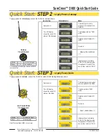
Step 2: Apply Power (Gateway) ........7
Step 3: Apply power (Node) ..............7
Step 4: Verify Communications .........8
Step 5: Site Survey ...........................9
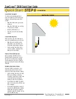
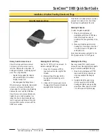
Step 6: Installation ...........................10
Maintenance/Parts Replacement ..........13
Host Network .........................................15
Product Dimensions ..............................17
Troubleshooting .....................................18
Accessories ...........................................21
FCC Notices ..........................................22
Table of Contents


