35
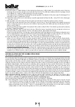
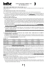
NOTES ON USE OF PROPANE (L.P.G.)
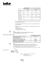
For pressure loss of 1 mbar flow rates must be increased by 45%;
For pressure loss of 2 mbar flow rates must be increases by 110%.
5) Burner
The burner must be ordered specifically for use with liquid gas (L.P.G.) so that it is equipped with gas valves of
sufficient dimensions to ensure correct ignition and gradual regulation. Our valves have dimension is planned for
use at a supply pressure of about 300 mm.W.C. We suggest gas pressure be checked at the burner by using a
water column pressure gauge.
N.B. Maximum and minimum burner pressure (kcal/h) obviously remains that of the original natural gas burner
(L.P.G. has heating power superior to that of natural gas. Therefore, in order to burn fully, it requires air
quantity in proportion to the thermal power created).
6) Combustion control
To limit consumption and avoid serious trouble, adjust combustion by using the appropriate instruments. It is
absolutely essential to check that the percentage of carbon monoxide (CO) does not exceed maximum permitted
value of 0,1 % (use a phial analyser or other similar instrument). Please note that our guarantee does not cover
burners operating on liquid gas (L.P.G.) in plant for which the above measures have not been taken.
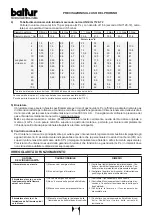
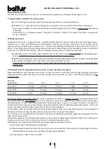
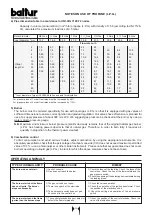
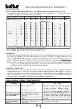
4) Pipe dimension table in accordance to UNI-CIG 7129-72 norms
Capacity in volume (consumption) in m
3
/h for propane (L.P.G.) with density of 1,56 (according to UNI 7128-
72), calculated for a maximum load loss of 0,5 mbar.
Outer diameter
3/8 Gas
½ Gas
3/4 Gas
1 Gas
1
1
/
4
Gas
1½Gas
2 Gas
2 ½ Gas
3 Gas
Inner diameter * mm
13,2
16,6
22,2
27,9
36,6
41,5
53,8
69,6
81,8
2
1,5
2,7
6,0
11
23
35
-
-
-
4
1,0
1,8
4,1
7,4
15
24
45
82
135
6
0,80
1,5
3,2
6,1
12
19
35
66
108
8
0,70
1,3
2,8
5,2
10,6
16,4
30
58
92
10
0,60
1,1
2,6
4,7
9,5
14,5
27
52
81
Virtual
15
0,50
0,90
2,0
3,8
7,6
11,5
21,5
43
65
length m
20
0,40
0,78
1,7
3,2
6,4
9,8
18,4
36
55
25
0,32
0,69
1,5
2,9
5,7
8,7
16,1
32
49
30
-
0,62
1,4
2,6
5,1
8,0
14,7
29
45
40
-
0,55
1,2
2,2
4,5
6,8
12,5
25
38
50
-
0,46
1,05
2,0
3,8
6,1
11,1
22
34
60
-
-
-
1,8
3,5
5,5
10,0
20
30
80
-
-
-
1,5
3,0
4,6
8,6
17
26
100
-
-
-
-
2,7
4,2
7,6
15
23
*
Inner diameter of pipe UNI 3824-68 taken as basis for calculation.
Flow rate m
3
/h
OPERATING ANOMALY
1) Check the fuses of the feed line. Check the fuses of the
control box. Check the line of the thermostats and the
gas pressure switch.
2) Check the opening of the detecting devices located along
the feeding pipes.
1) Check the valves operation.
2) Check the operation of the ignition transformer. Check
the position of the electrodes ends.
3) Check the setting and operation of the air pressure
switch.
1) Check the position of the control electrode. Check the
valve of the ionisation current.
TYPE OF IRREGULARITY
PROBABLE CAUSE
RIMEDY
The burner does not start.
The burner starts but the flame
does not ignite. The burner
stops consequently.
The burner starts and the flame
ignites then the burnes stops.
1) Lack of currente.
2) Gas does not reach the burner.
1) The gas valves do not open.
2) There is no spark at the electrode.
3) The air pressure switch does not give
it’s consent to the control box.
1) The control electrode does not detect or
detects the flame improperly.
Содержание SPARKGAS 3,6
Страница 14: ...14...
Страница 15: ...15...
Страница 16: ...16...
Страница 17: ...17...
Страница 27: ...27...
Страница 28: ...28...
Страница 29: ...29...
Страница 30: ...30...
Страница 40: ...40...
Страница 41: ...41...
Страница 42: ...42...
Страница 43: ...43...
Страница 53: ...53...
Страница 54: ...54...
Страница 55: ...55...
Страница 56: ...56...
Страница 66: ...66...
Страница 67: ...67...
Страница 68: ...68...
Страница 69: ...69...

