background image

20184179 (2) - 01/2021

Installation, use and maintenance instructions

Heavy oil burner

Three stage operation

CODE

MODEL

TYPE

3439347

PRESS 450 T/N

469 M1

GB

Содержание PRESS 450 T/N

Страница 1: ...20184179 2 01 2021 Installation use and maintenance instructions Heavy oil burner Three stage operation CODE MODEL TYPE 3439347 PRESS 450 T N 469 M1 GB ...

Страница 2: ...Translation of the original instructions ...

Страница 3: ...lation 14 6 1 Notes on safety for the installation 14 6 2 Handling 14 6 3 Preliminary checks 14 6 4 Operating position 15 6 5 Boiler plate 15 6 6 Blast tube length 15 6 7 Securing the burner to the boiler 16 6 8 Nozzle assembly 16 6 9 Electrodes adjustment 16 6 10 Nozzle installation 17 6 11 Fuel oil supply 18 6 12 Pump pressure 19 6 13 Electrical connections 20 7 Start up calibration and operatio...

Страница 4: ...Maintenance 27 9 1 Notes on safety for the maintenance 27 9 2 Maintenance programme 27 9 3 Opening and closing the burner 28 10 Faults Possible causes Solutions 29 A Appendix Accessories 31 B Appendix Electrical panel layout 32 ...

Страница 5: ...ith the following Technical Standards EN 12100 EN 267 According to the European Directives MD 2006 42 CE Machine Directive LVD 2014 35 UE Low Voltage Directive EMC 2014 30 UE Electromagnetic Compatibility The quality is guaranteed by a quality and management system certified in accordance with ISO 9001 2015 1 Declarations ...

Страница 6: ...rried out correctly may cause damage to the machine and or injury to people DANGER DANGER LIVE COMPONENTS This symbol indicates operations which if not carried out correctly lead to electric shocks with lethal consequences DANGER FLAMMABLE MATERIAL This symbol indicates the presence of flammable materials DANGER BURNING This symbol indicates the risks of burns due to high temperatures DANGER CRUSH...

Страница 7: ...event of damage to things or injury to people if such damage injury was due to any of the following causes incorrect installation start up use and maintenance of the burner improper incorrect or unreasonable use of the burner intervention of unqualified personnel carrying out of unauthorised modifications on the equipment use of the burner with safety devices that are faulty incorrectly applied an...

Страница 8: ...nance Only those parts envisaged by the manufacturer can be replaced 3 2 Personnel training The user is the person body or company that has acquired the machine and intends to use it for the specific purpose He is responsible for the machine and for the training of the people working around it The user undertakes to entrust the machine exclusively to suitably trained and qualified personnel undert...

Страница 9: ... N TC Emission C01 or Class 1 EN267 C02 or MZ Class 2 EN267 C03 or BLU Class 3 EN267 3N 400 50 230 50 BASIC DESIGNATION EXTENDED DESIGNATION 3N 400V 50Hz 3 230V 50Hz 230V 50 60Hz 110V 50 60Hz 140 450 Head TC Standard head TL Extended head Flame control system FS1 FS2 Standard 1 stop every 24 h Continuous operation only with the use of a flame detection electrode ionisation FS1 Three stage T N Modu...

Страница 10: ...s 50 7 E up to 500 65 E with kit Operation Intermittent min 1 stop every 24 hours Nozzle number 1 nozzle with return line Standard applications Boilers water steam diathermic oil Ambient temperature C 0 40 Combustion air temperature C max 60 Pump flow rate pressure range kg h bar 60 Weight of the burner complete with packaging kg 690 25 MODEL PRESS 450P N Electrical power supply V Hz 3 400 10 50 E...

Страница 11: ...ration phase 2560 225 5130 450 2nd STAGE Thermal power Output Minimum Maximum kW kg h kW kg h 1st nozzle ignition phase 855 75 1710 150 1st 2nd nozzle 1st stage of operation 1710 150 3420 300 1st 2nd 3rd nozzle 2nd stage of operation 2560 225 5130 450 3rd STAGE Thermal power Output Minimum Maximum kW kg h kW kg h 1st nozzle 1st stage of operation 855 75 1710 150 1st 2nd nozzle 2nd stage of operati...

Страница 12: ...requires the burner to be opened and the rear part drawn back on the slide bars Tab D 5 5 Standard equipment G L T T 1 P E D U U 1 M Fig 1 20186876 mm D E G L M P T T 1 U U 1 PRESS 450 T N 336 525 508 950 442 1090 435 565 1665 1820 Flexible hoses No 2 Grommet No 7 Screws No 4 Thermal flange gasket No 1 Nipples No 2 Nozzle No 3 Starter No 1 Manual No 1 Spare parts list No 1 ...

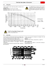
Страница 13: ... consult the manufacturer The firing rates were obtained in special test boilers according to EN 267 standard In Fig 3 you can see the diameter and length of the test combustion chamber Example Output 650 Mcal h 407 kW diameter 60 cm length 2 m MODULATING RATIO The modulating ratio obtained in test boilers according to standard EN 267 is 4 1 ATTENTION The FIRING RATE was obtained with an ambient t...

Страница 14: ...ew 5 Manometer plug 6 Vacuometer plug 7 Low limit thermostat 8 Electric board 9 Cable clamps 10 Control box reset push button and lock out lamp 11 Adjustment thermostat 12 Regulating bush for combustion head 13 Wiring terminal board 14 Ignition transformer 15 Filter 16 Valves group 17 Manometer 18 Lamp 19 Commutator 20 High limit thermostat 21 Timer Fig 4 D2802 ...

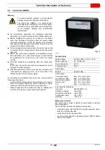
Страница 15: ...development of conden sate and humidity Otherwise before switching on again make sure that the entire control box is perfectly dry Static charges must be avoided since they can damage the control box s electronic components when touched Technical data Mechanical structure The control box is made of plastic to resist knocks heat and flame propagation The control box contains the following component...

Страница 16: ...fluoride halogen if present it is highly recommended to carry out cleaning and maintenance more frequently ATTENTION Burner handling operations can be highly dangerous if not carried out with the greatest attention distance unauthorised personnel check integrity and suitability of the means available Check also that the area in which you are working is empty and that there is an adequate escape ar...

Страница 17: ...t must be greater than the thickness of the boiler door complete with its fettling Tab F ATTENTION The burner is designed to work only in positions 1 and 4 Fig 7 Installation 1 is preferable as it is the only one that allows the maintenance operations as described in this manual The installation 4 permits the operation but makes the maintenance and inspection operations of the combustion head more...

Страница 18: ...s 3 the pin and split pin 2 6 8 Nozzle assembly At this installation stage the burner is still separated from the blast tube therefore it is possible to fit the nozzle with a 16 mm wrench Do not use any sealing products such as gaskets tape or sealants Be careful to avoid damaging the nozzle sealing seat 6 9 Electrodes adjustment Provide an adequate lifting system Be careful as some drops of fuel ...

Страница 19: ...ce CAUTION The use of nozzles other than those specified by Riello S p A and inadequate regular maintenance may result into emission limits non conforming to the values set forth by the regulations in force and in extremely serious cases into potential hazards to people and objects The manufacturing Company shall not be liable for any such damage arising from non observance of the requirements con...

Страница 20: ...on after than open the valves and supply normally the burner Key Explosion danger due to fuel leaks in the presence of a flammable source Precautions avoid knocking attrition sparks and heat Make sure the fuel shut off valve is closed before performing any operation on the burner ATTENTION The fuel supply line must be installed by qualified personnel in compliance with current standards and laws A...

Страница 21: ...ozzle Suggested pressure Light oil 25 bar Heavy oil 28 bar transformation kit Rated nozzles deliveries are listed on the table A tolerance of 5 concerns the real delivery against the rated one The pump leaves the factory set at 25 bar CAUTION Make sure that the hoses to the pump supply and return line are installed correctly ATTENTION During the installation hoses must not be stressed with twistin...

Страница 22: ... every 24 hours Refer to the wiring diagrams The electrical safety of the device is obtained only when it is correctly connected to an efficient earthing system made according to current standards It is necessary to check this fundamental safety requirement In the event of doubt have the electrical system checked by qualified personnel Do not use the gas tubes as an earthing system for electrical ...

Страница 23: ...Fig 15 the combustion head adjustment The adjustment should be made by turning the screw A Fig 16 till the set point Fig 15 is on the line with the washer B Fig 16 7 Start up calibration and operation of the burner ATTENTION The first start up of the burner must be carried out by qualified personnel as indicated in this manual and in compliance with the standards and regulations of the laws in for...

Страница 24: ...y Cams command air shutters adjustments Regolazioni camme comando valvole NOTE Never adjust the cams with sealed screws Cam 0 adjustment not necessary Positioned by the factory on the close shutters Cam ST2 for 2nd stage air shutters adjustment All group A moves by acting on cam ST2 Fig 18 Cam ST3 for 3rd stage air shutters adjustment All group B moves by acting on cam ST3 Fig 18 1st valve control...

Страница 25: ...and relative plate Maximum temperature thermostat Fig 21 this switches off the resistance when because of failure of the adjustment ther mostat the temperature of the pre heater increases to unaccept able levels a high temperature alarm output is provided on the burner terminal strip Factory setting is approximately 180 C Renewing the minimum and maximum temperature thermostats Reposition the prob...

Страница 26: ...age operation Fig 23 Lock out due to no ignition Normal Thermostat Motor Ignition transformer 1st flame valve 2nd flame valve Lock out lamp D2848 Pre purge 3rd flame valve ATTENTION Motor lock out It is caused by the over load relay when overload occurs or no current supply Periodically clean the filter of the pre heater tank ATTENTION Make sure that the mechanical locking systems on the adjustmen...

Страница 27: ...r of blinks indicates the reason for the malfunctioning refer to the coding in Tab J 8 1 4 Software diagnostics Gives an analysis of the life of the burner through optical connec tions with a PC showing the working hours number and types of lockout control box serial number etc To display the diagnostics proceed as follows Hold the button down for more than 3 seconds once the red LED burner lockou...

Страница 28: ...e opening of the 1st stage working valve Block out the UV sensor when the burner is operating the flame should switch off within 1 sec as also the repeti tion of the starting cycle and then the stopping of the burner Switch off the TL control device and then the TS device when the burner is operating the burner must stop ATTENTION Make sure that the mechanical locking systems on the various adjust...

Страница 29: ...or whenever necessary suck any water or other impurities present on the bottom of the tank using a separate pump Pump Unusual noise must not be evident during pump operation If the pressure is unstable or the pump runs noisily the flexible hose must be detached from the line filter and the fuel must be sucked from a tank located near the burner This measure permits the cause of the anomaly to be t...

Страница 30: ...ars or 250 000 operation cycles Pressure adjuster 15 years Servomotor electronic cam 10 years or 250 000 operation cycles Oil valve solenoid 10 years or 250 000 operation cycles Oil regulator 10 years or 250 000 operation cycles Pipes oil fittings metallic 10 years Flexible hoses if present 5 years or 30 000 pressurised cycles Fan impeller 10 years or 500 000 start ups DANGER Disconnect the electr...

Страница 31: ...ut at the end of the safety time No fuel in the tank air sucked Fuel level too high or water on the bottom of the Head and air damper adjusted Adjust Light oil solenoid valves do not Check the connections replace the coil 1st nozzle clogged dirty or Replace The ignition electrodes are Adjust or clean Electrode grounded due to bro Replace Faulty or grounded high voltage Replace High voltage cable d...

Страница 32: ...se Suction filters dirty Clean Suction valves closed Open them The paraffin solidifies due to the Put additive in the light oil Pump unprimes after pro longed pause Return pipeline not immersed in Bring it to the same height as the suction line Air in the suction line Tighten the couplings The pump is losing light oil Leak from sealing organ Replace the pump Flame with smoke Little air Adjust the ...

Страница 33: ...0376 Burner Code PRESS 450 T N 3000731 Burner Code PRESS 450 T N Diameter 1 1 2 60 E at 50 C 3010022 Thermostatic heater with LED 3010060 Heater 3010061 Thermostat two stage modulating 3010062 Burner Code PRESS 450 T N 3010012 Burner Code PRESS 450 T N 3000721 Burner Code PRESS 450 T N 3000751 Burner Code PRESS 450 T N 3000750 Burner Code PRESS 450 T N 3002719 Burner Code PRESS 450 T N 3010386 ATT...

Страница 34: ...ical panel layout Index of layouts 2 Reference indication 3 RMO 88 functional layout 4 RMO 88 functional layout 5 Functional layout 6 Functional layout 7 Electrical wiring that is the responsibility of the installer 1 2 Sheet no 1 A1 Coordinates Reference indication ...

Страница 35: ...33 20170392 GB Appendix Electrical panel layout 0 1 1 1 ...

Страница 36: ...20170392 34 GB Appendix Electrical panel layout ...

Страница 37: ...35 20170392 GB Appendix Electrical panel layout 0 1 0 2 3 2 3 ...

Страница 38: ...20170392 36 GB Appendix Electrical panel layout 0 0 ...

Страница 39: ...37 20170392 GB Appendix Electrical panel layout 0 1 2 3 445 445 3 445 6 0 7 445 8 8 8 9 8 8 8 8 8 8 8 8 8 8 8 9 8 ...

Страница 40: ... L3 3rd stage signalling MB Burner terminal board MV Fan motor Q2 Three phase disconnecting switch Q3 Three phase disconnecting switch RS Reset button RT1 PT100 probe S Pre heater tank SM Servomotor S1 Selector SA Alarm high oil temperature TL Limit thermostat TS Safety thermostat T2 2nd stage thermostat T3 3rd stage thermostat TA Ignition transformer TB Burner earth TE Electronic thermostat Tm Mi...

Страница 41: ......

Страница 42: ......

Страница 43: ......

Страница 44: ...Subject to modifications RIELLO S p A I 37045 Legnago VR Tel 39 0442 630111 http www riello it http www riello com ...

Отзывы: