6
english
3.1
Initializing
After the VARAN network is powered, the manager looks
for connected splitter ports and automatically assigns
addresses to the attached clients. It reads out the Data
Object List of the client, identifies the device and vendor.
The PLL of the client must be initialized for proper
operation. Until the initialization of the PLL is not finished,
the device is in idle state.
3.2
Synchronizing the client
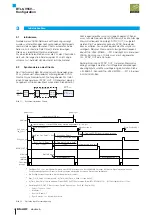
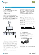
The client is synchronized with the bus cycle using a PLL
which is, in turn, synchronized with the global SYNC
message. The output of the PLL drives a pulse generator
(SYNC_OUT_0 generator) whose output is used to start
the measurement cycle. See figure Fig. 3-1.
Fig. 3-1:
SYNC
MAC
VARAN
PLL
Generator
PLL of the VARAN client
Position
Measurement
control
Start
Measurement
SYNC_OUT_0
PLL_SYNC_OUT
SYNC_OUT_0
PLL_SYNC_IN
message
from
master
Synchronizing client
However the measurement cycle frequency is limited, so if
the VARAN bus cycle frequency exceeds the allowed
measurement cycle frequency then the SYNC_OUT_0
must be divided. The pulse generator can divide the SYNC
period of the bus to decrease the frequency of the
measurement cycle. For example: the maximum permitted
measurement frequency of a BTL6-V55V-M0600-…-S115
is 2 kHz. With a 10 kHz VARAN bus cycle, the
PLL_SYNC_OUT must be divided by 5 by the pulse
generator.
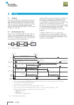
In addition, the SYNC_OUT_0, which queries the
measurement cycle, can be delayed to set the shortest
possible measurement delay in closed loop applications.
See Fig. 3-2 as an example: BTL6-V55V-M0150-…-S115
sensor in a 4 kHz VARAN bus.
3
Startup
global sync
system period (250 µs)
system period (250 µs)
global sync
Store Position N
Store Position N+1
Store Position N–1
PLL_Sync_Out_Delay
2
= 0 ns
Sync_Out_0_Delay
3
(250 – 112 µs)
Start US wave
Measurement N
Measurement N+1
transmit delay + constant FPGA delay (routing dependent e.g. ~6.4 µs)
Time until TPDO read command received
Acquisition Delay =
112 µs + data read delay
CPU sync
PLL_sync_out
SYNC_OUT_0
5
US wave
runtime
(MGate)
Calculating
position
PLL_sync_in
1
(vb_sync)
Al_Time_Until_Data_is_Valid
4
112 µs
1)
PLL_sync_in signal is generated by VARAN MAC when a SYNC message is received. This signal stores the new position information.
The isochronous messages are received directly after it.
2)
The routing delay is not corrected in this example.
3)
Sync_Out_0_Delay = system period - AI_Time_Until_Data_is_Valid => see 5 also
4)
AI_Time_Until_Data_is_Valid is obtained from EM75 0x611E object. It is 112 µs in case of BTL-V55V-M0150-
…
-S115.
5)
SYNC_OUT_0 setting (for details see „Design Spec Varan – Rev 0.86“, chapter PLL):
–
Offset : 13800 => 138us
–
Multiplier: 1
–
Sync out Enable: 1
–
Sync Selector: 1 => System SyncStore
Fig. 3-2: Adjusting measurement delay
BTL6-V55V…
Configuration
Содержание BTL6-V55 Series
Страница 1: ...BTL6 V55 Konfigurationshandbuch deutsch...
Страница 2: ...www balluff com...
Страница 15: ...BTL6 V55 Configuration Manual english...
Страница 16: ...www balluff com...

