4-10 Input / Output
MN1957
www.baldormotion.com
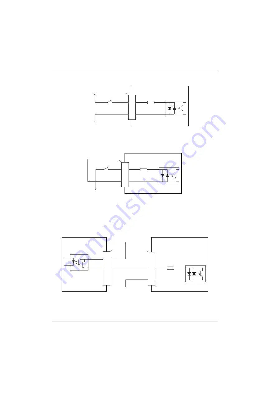
4.3.1.5 Typical digital input wiring
Figure 12: Digital input - typical ‘active high’ input connection using a switch
Figure 13: Digital input - typical ‘active low’ input connection using a switch
Note:
The circuits shown in Figures 12 and 13 are not suitable for use with fast inputs
DIN0 to DIN3. Using a mechanical switch, relay contacts or other source liable
to signal ‘bounce’ could cause unwanted multiple triggering.
Figure 14: Digital input - typical connections from a Baldor MicroFlex
NextMove E
S
B-2
D
IN
4
U
ser
supp
l
y
24V
U
ser
supp
l
y
GN
D
X9
8
9
CR
E
F
1
TLP
280
D
IN
4
U
ser
supp
l
y
GN
D
CR
E
F
1
NextMove E
S
B-2
X9
8
9
TLP
280
U
ser
supp
l
y
24V
NextMove E
S
B-2
MicroFlex
/
e
q
ui
p
ment out
p
ut
D
IN
4
Status
-
U
ser
supp
l
y
24V
U
ser
supp
l
y
GN
D
X9
X
3
8
2
3
9
CR
E
F
1
NEC
PS
2562
L
-1
TLP
280
Servo Systems Co. • 115 Main Road • P.O. Box 97 • Montville, NJ,
07045-0097 • (973) 335-1007 • Toll Free: (800) 922-1103
Fax: (973) 335-1661 • www.servosystems.com


