MN715J
Receiving and Installation 3-9
3 Phase Installation
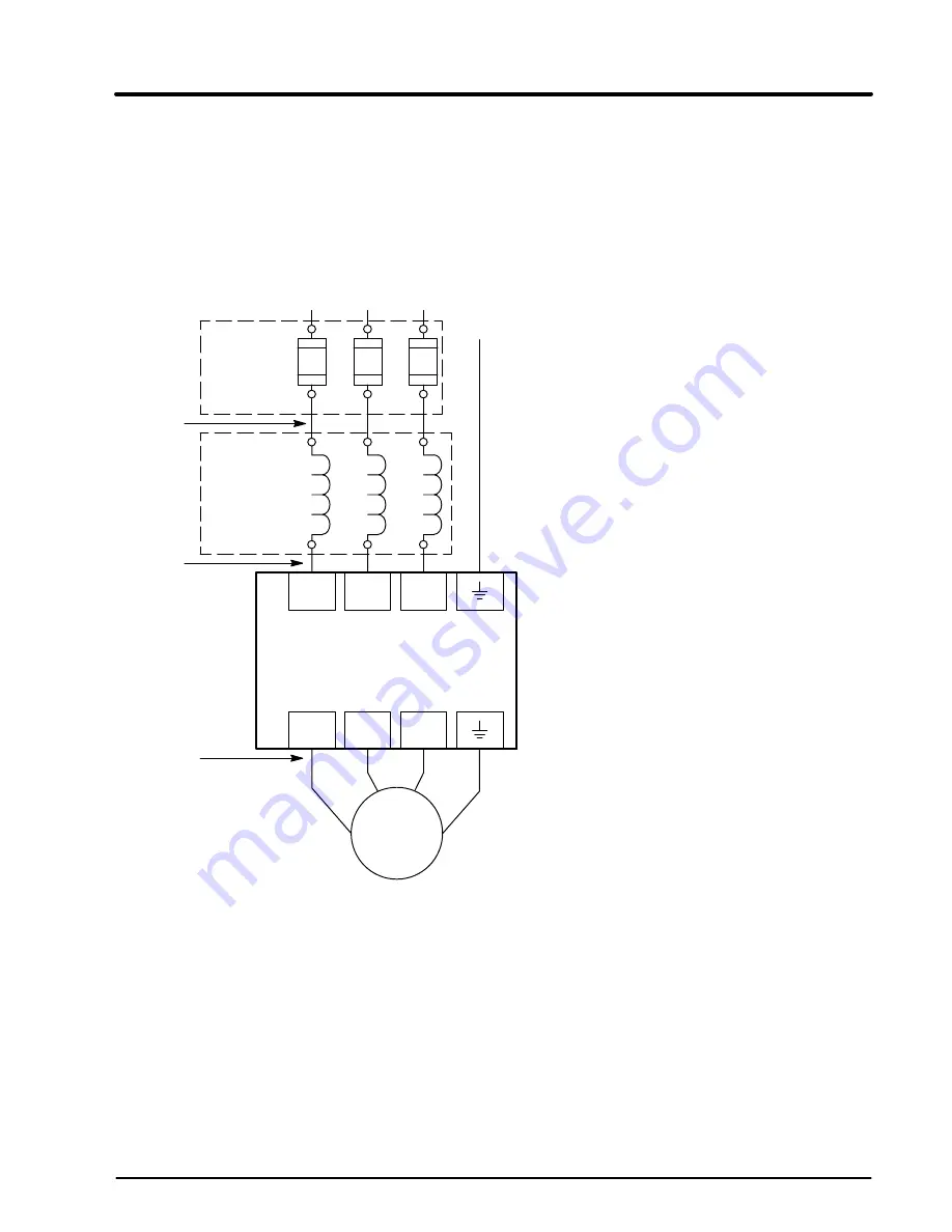
The AC power and motor connections are shown in Figure 3-4. The 15J
control has electronic I
2
t motor overload protection. If motor overloads are
desired, they should be sized according to the manufacturers specifications
and installed between the motor and the T1, T2 and T3 terminals of the
control. Refer to Figure 3-3 for terminal locations.
Figure 3-4 3 Phase AC Power and Motor Connections
L1
L2
L3
L1
L2
L3
Earth
*
AC Motor
Note 2
Note 3
Baldor
Series 15J
Control
*
Optional
Line
Reactor
Note 1
Note 3
Note 3
A1
B1
C1
A2
B2
C2
T1
T2
T3
Note 4
T1
T2 T3
G
Notes:
1.
See Protection Devices described in this section.
2.
Use same gauge wire for Earth ground as is used for L1, L2 and L3.
3.
Metal conduit should be used. Connect conduits so the use of a reactor or RC device
does not interrupt EMI/RFI shielding.
4.
See Line/Load Reactors described previously in this section.
*
Optional components not
provided with 15J Control.
*
Optional
Fusing
Содержание ID15J101-ER
Страница 1: ...Series 15J Inverter Control 7 04 MN715J Installation and Operating Manual ...
Страница 5: ...iv Table of Contents MN715J ...
Страница 11: ...2 4 General Information MN715J ...
Страница 59: ...4 22 Programming and Operation MN715J ...
Страница 75: ...6 6 Specifications and Product Data MN715J ...
Страница 79: ...A 4 Dynamic Brake Hardware MN715J ...
Страница 86: ...Appendix C Remote Keypad Mounting Template MN715J Remote Keypad Mounting Template C 1 ...


