


Page
59
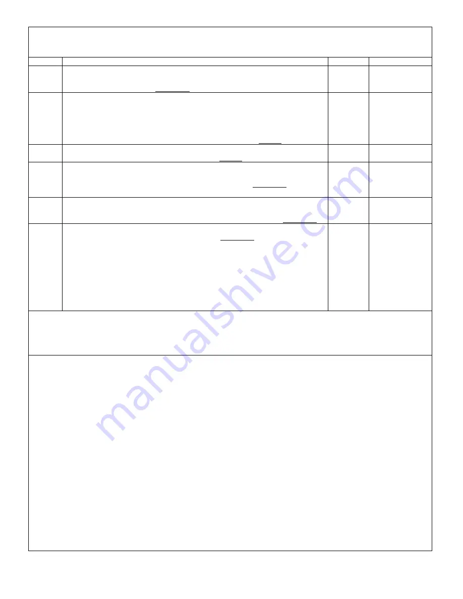
Section 19
Maintenance & Inspection
Dragonfly 912
AILERON SUPPORT TUBES & MOUNTING
STEP
INSTRUCTIONS
for Assembly, for Disassembly reverse the order!
PART NO.
STAGE CERT.
1
Bolt AN4-30A, 1/4” washer,
strut plate A,
wing spar leading edge,
strut plate B,
1/4” washer, AN4 full nut.
Very tight.
DFL 004
DFL 005
2
Bolt AN4-30A, 1/4” washer, wing comp strut saddle channel brkt, wing comp
strut, wing comp strut saddle channel brkt, fabric wing sail,
saddle 1” aileron angle,
aileron supp tube,
saddle angle aluminium, (inboard aileron support tube gets wing to main
boom cable after saddle angle aluminium), AN4 half nut.
Loose.
DFP 021
DFC 021
3
Bolt AN3-21A, saddle angle aluminium, aileron supp tube, fabric wing sail,
wing comp strut, 3/16” washer, AN3 half nut.
Loose.
4
Bolt AN3-21A, 3/16” washer, wing comp strut, fabric wing sail, aileron supp
tube, saddle angle aluminium,
threaded insert 1/2” x 10/32 TPI
(hole in insert should be parallel with wing comp strut).
Very tight.
Tighten
bolts
#
2 &
#
3
DFO 040
5
Bolt AN4-5A, cable
wing – tail upper,
wing – tail lower,
wing comp strut saddle channel brkt, 1/4” washer, AN4 half nut.
Very tight.
DFQ 004
DFQ 001
6
Bolt AN4-27A, hinge point,
spacer aileron hinge 1.125”,
aileron supp tube, 1/4” washer, AN4 half nut.
Very tight.
Setting Aileron Angle: Using “Smart Level”. Set ailerons at 16.5 degrees down
compared to Root Tube. Set Level to Zero on Root Tube. Measure angle of Aileron
at inboard part of outer frame, where it is not affected by fabric angles. Adjust using
Ball Joint Rod Ends on Aileron Linkages, both top and bottom,( this occasionally
requires shortening the treads on Ball End Joints by as much as ¼”), and tighten
jamb nuts. (Note: Be sure to hold stick centred during this process.)
DFG 002
(1)
Recommended Special Tools:
Smart Level (digital level)
(2)
The parts needed to perform the task:
Replace worn/damaged parts as needed, listed above. Max. Wear (defined 1.1.8.1)
(3)
Type of maintenance:
Inspection=Line & Replacement=Heavy
(when it involves replacement of structural components.)
(4)
Certification needed to accomplish the task:
Line=LSRI Inspection or above, Heavy=LSRM Maintenance or above.
see:
3 Level of Certification in this manual
(5)
Detailed instructions and diagrams as needed to perform the task, listed above and adjacent page.
Every Annual or 100 Hrs., Inspect for Cracks, Corrosion, Elongation of holes & Fasteners for Wear & Security.
See: 1.3.5 Fabric Coverings: For more inspection and testing information on fabric coverings.
See
Cables, Thimbles and Tangs Page 16
(6)
Method to test/inspect to verify the task was accomplished properly.
Insure that all procedures were followed correctly
and there is proper non-binding movement to moving parts and that fasteners were tightened as instructed. When flight
controls are involved, assure that they are operating properly.
Section 19 Aileron Support Tubes & Mounting
Section 19
Содержание 912 Dragonfly
Страница 3: ...Page 2 ...
Страница 4: ...Page 3 ...
Страница 5: ...Page 4 ...
Страница 25: ...Page 24 Drawing 1 ...
Страница 27: ...Page 26 Drawing 2 ...
Страница 29: ...Page 28 Drawing 3 ...
Страница 31: ...Page 30 Drawing 4 ...
Страница 33: ...Page 32 Drawing 5 ...
Страница 35: ...Page 34 Drawing 6 ...
Страница 37: ...Page 36 Note for Hydraulic Brakes see Appendix B Drawing 7 ...
Страница 39: ...Page 38 Drawing 8 ...
Страница 41: ...Page 40 Drawing 9 ...
Страница 43: ...Page 42 Drawing 10 ...
Страница 45: ...Page 44 Drawing 11 ...
Страница 47: ...Page 46 Drawings 12A 12B ...
Страница 49: ...Page 48 Drawing 13 ...
Страница 51: ...Page 50 Drawing 14 ...
Страница 53: ...Page 52 Drawing 15 ...
Страница 55: ...Page 54 Drawing 16 ...
Страница 57: ...Page 56 Drawing 17 ...
Страница 59: ...Page 58 Drawing 18 ...
Страница 61: ...Page 60 Drawing 19 ...
Страница 63: ...Page 62 Drawing 20 ...
Страница 65: ...Page 64 Drawing 21 ...
Страница 67: ...Page 66 Drawing 22 ...
Страница 69: ...Page 68 Drawing 23 ...
Страница 71: ...Page 70 Drawing 24 ...
Страница 73: ...Page 72 Drawing 25 ...
Страница 75: ...Page 74 Drawing 26 ...
Страница 77: ...Page 76 Drawing 27 ...
Страница 79: ...Page 78 Wiring1 jpg Drawing 28a ...
Страница 80: ...Page 79 Wiring2 jpg Drawing 28b ...
Страница 81: ...Page 80 elecLights jpg Drawing 28c ...
Страница 83: ...Page 82 Drawing 29 ...
Страница 85: ...Page 84 Drawing 30 ...
Страница 92: ...Page 91 Appendix B Brakes Manual for BX1320 BX1000 Appendix B Page 1 ...
Страница 93: ...Page 92 Appendix B Page 2 ...
Страница 94: ...Page 93 Appendix B Page 3 ...
Страница 96: ...Page 95 Appendix B Page 5 ...
Страница 97: ...Page 96 Appendix B Page 6 ...
Страница 98: ...Page 97 Appendix B Page 7 ...
Страница 104: ...Page 103 Figure 1a Description of Display Pages ...
Страница 105: ...Page 104 Figure 1b Description of Display Pages ...
Страница 138: ...Page 137 Appendix C EIS 4000 912 914 ...
Страница 139: ...Page 138 Appendix C EIS 4000 912 914 ...
Страница 140: ...Page 139 Appendix C EIS 4000 912 914 ...
Страница 141: ...Page 140 Appendix C EIS 4000 912 914 End Appendix C ...
Страница 155: ...Page 154 Appendix E2 Powerfin Prop Page 2 ...
Страница 156: ...Page 155 Appendix E2 Powerfin Prop Page 3 ...
Страница 157: ...Page 156 Appendix E2 Powerfin Prop Page 4 ...
Страница 158: ...Page 157 Appendix E2 Powerfin Prop Page 5 ...
Страница 159: ...Page 158 Appendix E2 Powerfin Prop Page 6 ...
Страница 160: ...Page 159 Appendix E2 Powerfin Prop Page 7 ...
Страница 161: ...Page 160 Appendix E2 Powerfin Prop Page 8 ...
Страница 162: ...Page 161 Appendix E2 Powerfin Prop Page 9 ...
Страница 163: ...Page 162 Appendix E2 Powerfin Prop Page 10 ...
Страница 164: ...Page 163 Appendix E2 Powerfin Prop Page 11 End of Appendix E2 ...
Страница 187: ...Page 186 By Memphis Soaring FIGURE 3 Common Signals ...


