Page
115
Crimp the mating connectors onto the extension wire. Plug the color-coded leads onto the matching
color extension wires. Secure the probe leads with suitable wire clamps to prevent them from chaffing
against the engine or airframe. Heat shrink tubing can be used to protect the leads from abrasion, and
insulate the electrical connections to the probe.
NOTE :
The length of wire on the EGT & CHT probes, or the extension wire may be shortened as
desired for your installation.
5.3
Verify the Wiring – A Quick Check
Take a moment now to review all wiring connections you have made to the EIS. Double check the
following wiring:
a) power
b) ground
c) tachometer connections
d) Verify that the same ground wire is not used as both a ground to the engine for the EIS, and as a
ground for the ignition kill switches. Verify that these separate ground leads do not connect to the
engine in such a way that they could be become disconnected from the engine, but remain connected
together. Do not use the same connection to the engine for these ground leads.
Finally, install the connector backshell using the supplied hardware. Secure the wiring, using cable
clamps to the aircraft structure so that no strain is transmitted to the connector. Plug the connectors
into the EIS and secure them to the instrument with the screws included with the back shell.
6.
Check-Out
6.1
Initial Application of Power to the Instrument
Apply power to the system Verify that the LCD display becomes active. The instrument will be on
display page 0. If this operation is not observed, immediately turn off power to the EIS and recheck all
wiring---especially power, ground, 4.8V excitation output and 12V fuel flow power output.
At this point, you may wish to completely configure the instrument for your installation. Refer the
section “Configuring the EIS for your Installation”.
6.2
Tachometer Initial Test
Turn on the EIS. The tachometer will display 0 when the engine is not operating. Refer to the
“Configuration Set Pages” section, and set the TachP/R according to the type of engine you have.
Turn off the EIS. Start the engine; turn on the EIS and verify that the tachometer reading is active and
appears reasonable.
6.2.1
Testing Tachometer Inputs
Two inputs are provided for the tachometer sensing. The EIS will use tachometer input 1 when a
tachometer signal is sensed. If tachometer input #1 is not providing any RPM indication, the EIS will
use the tachometer input #2. Each input must be tested to make sure it is functioning. This test is
accomplished by turning off tachometer input #1 (such as by turning off the magneto), and observing
is tachometer input #2 provides an accurate and stable tachometer reading. Repeat this by turning off
the tachometer input #2 and verifying the tachometer input #1 is accurate and stable.
Содержание 912 Dragonfly
Страница 3: ...Page 2 ...
Страница 4: ...Page 3 ...
Страница 5: ...Page 4 ...
Страница 25: ...Page 24 Drawing 1 ...
Страница 27: ...Page 26 Drawing 2 ...
Страница 29: ...Page 28 Drawing 3 ...
Страница 31: ...Page 30 Drawing 4 ...
Страница 33: ...Page 32 Drawing 5 ...
Страница 35: ...Page 34 Drawing 6 ...
Страница 37: ...Page 36 Note for Hydraulic Brakes see Appendix B Drawing 7 ...
Страница 39: ...Page 38 Drawing 8 ...
Страница 41: ...Page 40 Drawing 9 ...
Страница 43: ...Page 42 Drawing 10 ...
Страница 45: ...Page 44 Drawing 11 ...
Страница 47: ...Page 46 Drawings 12A 12B ...
Страница 49: ...Page 48 Drawing 13 ...
Страница 51: ...Page 50 Drawing 14 ...
Страница 53: ...Page 52 Drawing 15 ...
Страница 55: ...Page 54 Drawing 16 ...
Страница 57: ...Page 56 Drawing 17 ...
Страница 59: ...Page 58 Drawing 18 ...
Страница 61: ...Page 60 Drawing 19 ...
Страница 63: ...Page 62 Drawing 20 ...
Страница 65: ...Page 64 Drawing 21 ...
Страница 67: ...Page 66 Drawing 22 ...
Страница 69: ...Page 68 Drawing 23 ...
Страница 71: ...Page 70 Drawing 24 ...
Страница 73: ...Page 72 Drawing 25 ...
Страница 75: ...Page 74 Drawing 26 ...
Страница 77: ...Page 76 Drawing 27 ...
Страница 79: ...Page 78 Wiring1 jpg Drawing 28a ...
Страница 80: ...Page 79 Wiring2 jpg Drawing 28b ...
Страница 81: ...Page 80 elecLights jpg Drawing 28c ...
Страница 83: ...Page 82 Drawing 29 ...
Страница 85: ...Page 84 Drawing 30 ...
Страница 92: ...Page 91 Appendix B Brakes Manual for BX1320 BX1000 Appendix B Page 1 ...
Страница 93: ...Page 92 Appendix B Page 2 ...
Страница 94: ...Page 93 Appendix B Page 3 ...
Страница 96: ...Page 95 Appendix B Page 5 ...
Страница 97: ...Page 96 Appendix B Page 6 ...
Страница 98: ...Page 97 Appendix B Page 7 ...
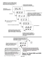
Страница 104: ...Page 103 Figure 1a Description of Display Pages ...
Страница 105: ...Page 104 Figure 1b Description of Display Pages ...
Страница 138: ...Page 137 Appendix C EIS 4000 912 914 ...
Страница 139: ...Page 138 Appendix C EIS 4000 912 914 ...
Страница 140: ...Page 139 Appendix C EIS 4000 912 914 ...
Страница 141: ...Page 140 Appendix C EIS 4000 912 914 End Appendix C ...
Страница 155: ...Page 154 Appendix E2 Powerfin Prop Page 2 ...
Страница 156: ...Page 155 Appendix E2 Powerfin Prop Page 3 ...
Страница 157: ...Page 156 Appendix E2 Powerfin Prop Page 4 ...
Страница 158: ...Page 157 Appendix E2 Powerfin Prop Page 5 ...
Страница 159: ...Page 158 Appendix E2 Powerfin Prop Page 6 ...
Страница 160: ...Page 159 Appendix E2 Powerfin Prop Page 7 ...
Страница 161: ...Page 160 Appendix E2 Powerfin Prop Page 8 ...
Страница 162: ...Page 161 Appendix E2 Powerfin Prop Page 9 ...
Страница 163: ...Page 162 Appendix E2 Powerfin Prop Page 10 ...
Страница 164: ...Page 163 Appendix E2 Powerfin Prop Page 11 End of Appendix E2 ...
Страница 187: ...Page 186 By Memphis Soaring FIGURE 3 Common Signals ...


