


Page
113
5.2.6
External Alarm Output
This output is used to control the external warning light included. The output is an OPEN/GROUND
type output. This means that when this output is off (the alarm is not active), this line is equivalent to
an OPEN circuit. When this output is on, this output is switched to GROUND. Thus, the external
warning light (or annunciator) is connected to this output and +12 Volts. The maximum current this
output can control is 0.11 Amperes, or 110 mA. Exceeding 110 mA will normally cause this output to
go to the open state, although it is possible to damage this output is the condition is not corrected.
5.2.7
Auxiliary Inputs
Your instrument includes 6 auxiliary inputs. Wire these inputs to your sensors for the auxiliary inputs
according to the sheets included with the auxiliary input sensors. Refer to the “Advice Before Starting
Your Installation” section at the front of this manual regarding assignment of the auxiliary inputs to the
various functions.
If you are using the auxiliary input for your own custom application, this input must be in the range of
0-5 Volts DC, and must not exceed 5.5 Volts. The scaling of this auxiliary display number n is set
using the “nSF” and “nOff” as described in the “Configuration Set Pages” section. If this input is not
used, the Aux limit should be set to zero on the “Set Limits” pages to prevent nuisance warnings.
CAUTION:
This input must not exceed 5.5 Volts. Although no damage will occur the accuracy of
the instrument will be adversely affected while an aux input exceeds 6.0 Volts.
5.2.8
Cylinder Head Temperature Probe Installation
Ring-terminal type CHT probes are installed by removing the spark plug, placing the sensor under it,
and re-installing the plug into the engine. Orient the sensor so that as much clearance as possible is
provided between its leads and the engine structure.
Bayonet type CHT probes (for Lycoming and Continental engines) are retained by a bayonet adapter.
This adapter is screwed into the engine, in a threaded hole near the bottom spark plug. This hole can be
identified by its solid bottom.
Do not use the primer hole to mount this adapter! If you are in doubt,
consult an expert!
The CHT probe is adjusted by turning the locking collar on the spring so that its tip
is pressed against the bottom of the CHT probe well when it is locked onto the adapter.
NOTE: To prevent false readings for inputs that are not used, it is recommended that unused CHT
inputs be shorted together. Unused EGT inputs may also be shorted together, or may be hooked up in
parallel with another EGT input so that the EGT Span calculation remains meaningful.
5.2.9
Exhaust Gas Temperature Probe Installation
Start by drilling an 1/8-inch diameter holes at the appropriate position in the exhaust manifold as
indicated by the engine manufacturer. If the manufacturer provides no guidance on the location of the
EGT probes, we recommend the following:
1) Position the probe 2-8 inches from the cylinder.
2) Although not critical, it is preferable to position all probes the same distance from the cylinder.
3) If possible, position the probes so that they are mounted on a straight (not curving) portion of the
exhaust manifold. The hose clamps fit slightly better on straight portions of the manifold.
Cont’d next page
Содержание 912 Dragonfly
Страница 3: ...Page 2 ...
Страница 4: ...Page 3 ...
Страница 5: ...Page 4 ...
Страница 25: ...Page 24 Drawing 1 ...
Страница 27: ...Page 26 Drawing 2 ...
Страница 29: ...Page 28 Drawing 3 ...
Страница 31: ...Page 30 Drawing 4 ...
Страница 33: ...Page 32 Drawing 5 ...
Страница 35: ...Page 34 Drawing 6 ...
Страница 37: ...Page 36 Note for Hydraulic Brakes see Appendix B Drawing 7 ...
Страница 39: ...Page 38 Drawing 8 ...
Страница 41: ...Page 40 Drawing 9 ...
Страница 43: ...Page 42 Drawing 10 ...
Страница 45: ...Page 44 Drawing 11 ...
Страница 47: ...Page 46 Drawings 12A 12B ...
Страница 49: ...Page 48 Drawing 13 ...
Страница 51: ...Page 50 Drawing 14 ...
Страница 53: ...Page 52 Drawing 15 ...
Страница 55: ...Page 54 Drawing 16 ...
Страница 57: ...Page 56 Drawing 17 ...
Страница 59: ...Page 58 Drawing 18 ...
Страница 61: ...Page 60 Drawing 19 ...
Страница 63: ...Page 62 Drawing 20 ...
Страница 65: ...Page 64 Drawing 21 ...
Страница 67: ...Page 66 Drawing 22 ...
Страница 69: ...Page 68 Drawing 23 ...
Страница 71: ...Page 70 Drawing 24 ...
Страница 73: ...Page 72 Drawing 25 ...
Страница 75: ...Page 74 Drawing 26 ...
Страница 77: ...Page 76 Drawing 27 ...
Страница 79: ...Page 78 Wiring1 jpg Drawing 28a ...
Страница 80: ...Page 79 Wiring2 jpg Drawing 28b ...
Страница 81: ...Page 80 elecLights jpg Drawing 28c ...
Страница 83: ...Page 82 Drawing 29 ...
Страница 85: ...Page 84 Drawing 30 ...
Страница 92: ...Page 91 Appendix B Brakes Manual for BX1320 BX1000 Appendix B Page 1 ...
Страница 93: ...Page 92 Appendix B Page 2 ...
Страница 94: ...Page 93 Appendix B Page 3 ...
Страница 96: ...Page 95 Appendix B Page 5 ...
Страница 97: ...Page 96 Appendix B Page 6 ...
Страница 98: ...Page 97 Appendix B Page 7 ...
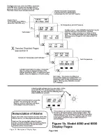
Страница 104: ...Page 103 Figure 1a Description of Display Pages ...
Страница 105: ...Page 104 Figure 1b Description of Display Pages ...
Страница 138: ...Page 137 Appendix C EIS 4000 912 914 ...
Страница 139: ...Page 138 Appendix C EIS 4000 912 914 ...
Страница 140: ...Page 139 Appendix C EIS 4000 912 914 ...
Страница 141: ...Page 140 Appendix C EIS 4000 912 914 End Appendix C ...
Страница 155: ...Page 154 Appendix E2 Powerfin Prop Page 2 ...
Страница 156: ...Page 155 Appendix E2 Powerfin Prop Page 3 ...
Страница 157: ...Page 156 Appendix E2 Powerfin Prop Page 4 ...
Страница 158: ...Page 157 Appendix E2 Powerfin Prop Page 5 ...
Страница 159: ...Page 158 Appendix E2 Powerfin Prop Page 6 ...
Страница 160: ...Page 159 Appendix E2 Powerfin Prop Page 7 ...
Страница 161: ...Page 160 Appendix E2 Powerfin Prop Page 8 ...
Страница 162: ...Page 161 Appendix E2 Powerfin Prop Page 9 ...
Страница 163: ...Page 162 Appendix E2 Powerfin Prop Page 10 ...
Страница 164: ...Page 163 Appendix E2 Powerfin Prop Page 11 End of Appendix E2 ...
Страница 187: ...Page 186 By Memphis Soaring FIGURE 3 Common Signals ...


