background image

Test Procedure

© b2 electronic GmbH

DHV0086 Rev06

62

5�3�3 

Configuring an Auto Test Sequence on the HVA Unit

Steps AS1-AS15 describe how to configure a test sequence.

Step

Procedure 

(Configure automatic sequence)

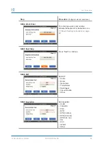
AS01: Edit Sequences

Select “Edit Sequences”.

AS02: Edit or New

The “Edit Sequences” menu displays the 

sequences already stored in memory. 

To modify an existing sequence, select the 

corresponding sequence from the list and 

select the “EDIT” option on the list. 

To create a new sequence, select the 

“New” option on the right-hand side of the 

screen.

AS03: Title

For entering a test sequence title, activate 

the keyboard and type the title.

Содержание HVA Series

Страница 1: ...Set with Tan Delta Firmware V2 E N G L I S H DHV0086 Rev06 b2 electronic GmbH Riedstrasse 1 6833 Klaus Austria T 43 0 5523 57373 F 43 0 5523 57373 5 www b2hv at info b2hv at Subject to alterations Err...

Страница 2: ...b2 electronic GmbH DHV0086 Rev06 2...

Страница 3: ...4 2 User Interface 20 4 3 Instrument Setup 25 4 4 Operation Modes 32 5 Test Procedure 36 5 1 Equipment setup 36 5 2 Manual Test Mode 40 5 3 Automatic Test Mode 55 5 4 Interrupting a Test 73 5 5 Disch...

Страница 4: ...lowing is a guideline indicating the most significant information as a function of the user s responsibilities User Responsibilities Focus HVA operator Connecting the equipment Carrying out manual or...

Страница 5: ...t in death or serious injury Caution CAUTION Indicates a hazardous situation which if not avoided could result in minor or moderate injury Notice NOTICE Indicates suggested practices to protect equipm...

Страница 6: ...k and comprehensive support and the product data base The b2 Customer Portal is exclusively reserved for b2 electronic customers Register now for Information about meetings and training sessions Docum...

Страница 7: ...ur discretion Equipment that is returned to b2 must be packed in original packaging All shipped items must be prepaid and insured No other warranties are expressed or implied Contact Information b2 el...

Страница 8: ...d earthing procedures All procedures must comply with local safety regulations Always treat exposed connectors and conductors as potential electric shock hazards Device under Test DUT must be earthed...

Страница 9: ...d of the risks involved WARNING Radiation Hazard Testing vacuum bottles above their rated voltage with DC can produce dangerous X rays NOTICE Equipment Handling DUT must have clean connections Testing...

Страница 10: ...e loads Generators Switchgear Transformers Rotating machines Insulators Bushings Appropriate measurements Measurement Examples Test Capacitance Resistance Dielectric breakdown voltage RMS current Appl...

Страница 11: ...ce Time Flashover Voltage Tan delta measurement accuracy 1 x 10 4 optional Duty cycle Continuous No thermal limitation on operating time Test modes manual automatic Output modes AC VLF Symmetrical and...

Страница 12: ...ge Tan delta measurement accuracy 1 x 10 4 optional Duty cycle Continuous No thermal limitation on operating time Test modes manual automatic Output modes AC VLF Symmetrical and load independent acros...

Страница 13: ...e Tan delta measurement accuracy 1 x 10 4 optional Duty cycle Continuous No thermal limitation on operating time Test modes manual automatic Output modes AC VLF Symmetrical and load independent across...

Страница 14: ...ntation Arc management To provide short circuit protection To allow for fault conditioning Limits test interruptions commonly encountered when using conventional HV testing instruments that immediatel...

Страница 15: ...tion Facilitates test repetition IP67 with closed lid To avoid damage during transport or storage To protect instrument from water Protects instrument Improves functionality 3 3 External Interlock and...

Страница 16: ...r Cord EF C13 10 A 3 m black 1 KDD0012 USB Pen Flash Drive b2 1 DHV00861 User Manual EN 1 PC software 1 HVA28 Accessories The following items are included in the HVA28 delieveries Art Nr Item Image pc...

Страница 17: ...kV TD 5 m MC14 1 VK0060 HVA34 1 HVA45 card board 585 x 383 x 700 mm 1 VKR0045 HVA45 Lap top bag for accessories 1 HVA34TD 1 HVA45TD Accessories The following items are included in the HVA34TD 1 and HV...

Страница 18: ...onnection components are located on the front panel Location Description Front Panel Test controls and emergency shutdown HV status information Cable and power source connections Air vent USB HVA28 HV...

Страница 19: ...up or down Rotate To enter selection Click push in 42 Emergency OFF button Activates emergency shutdown Device operation is only possible if the Emergency OFF button is deactivated To activate Emerge...

Страница 20: ...e and time Indicates day date and time USB Indicates if USB is enabled green or disabled red Bluetooth Indicates if Bluetooth is enabled green or disabled red Scroll button If active scroll up or down...

Страница 21: ...ge options shown on the HVA display screen 70 Rotate Push in Click To move to another item in a menu list or to any other field possible on the screen currently displayed rotate the knob To scroll thr...

Страница 22: ...stion This screen indicates a user interaction question Consider the information on the screen and make your choice by selecting Yes or No Warning This screen shows a warning Press OK to confirm Error...

Страница 23: ...to enter a user selected name Possible entries are A B C D E F G H I J K L M N O P Q R S T U V W X Y Z 0 space _ 0 1 2 3 4 5 6 7 8 9 Situation Procedure Activate Naming To select characters rotate kno...

Страница 24: ...To delete characters select the backspace symbol and press Enter Press and hold Enter for auto repeat Cancel Changes To cancel your changes in the text field select the cancel symbol and press Enter S...

Страница 25: ...prior to the HVA s first use Settings can be modified anytime You will find the selection option Instrument Setup in the main menu under Settings 4 3 1 Setup Steps IS1 IS7 describe how to setup the in...

Страница 26: ...at the appropriate screen and set date and time IS4 Reporting Select the appropriate reporting type Disabled Basic reporting Extended reporting Basic reporting only states the DUT type and a title whe...

Страница 27: ...its Select metric or imperial units When imperial is selected the temperature unit is also set to F IS7 Update from USB This function is used when installing updates and for transferring information f...

Страница 28: ...Procedure System Information SI1 Settings Select Settings SI2 System Information Select System Info SI3 System Information System Information displays HVA characteristics This information cannot be m...

Страница 29: ...ings L2 Language and Region Select Language and Region L3 Language Choose language Select from different options depending on the firmware version L4 Region Choose region Select from different options...

Страница 30: ...p Procedure Sequences and reports SRM1 Settings Select Settings SRM2 Data Administration Select Data Administration SRM3 Delete All Sequences To delete all sequences select Delete all Sequences SRM4 I...

Страница 31: ...To delete all reports select Delete all Reports SRM6 Export Reports To export the stored reports on the unit insert a USB flash drive and select this function All reports will be automatically writte...

Страница 32: ...Mode on page 40 and see 5 3 Automatic Test Mode on page 55 Test mode Characteristics Manual Designed to facilitate rapid testing Test parameters of the last manual test appear as the default settings...

Страница 33: ...ing extruded cables e g XLPE cables and other DUTs Measured values shown as RMS VLF Tan Delta Measurement VLF TD Sine wave Measures the Tan Delta value of the DUT according to selectable standards and...

Страница 34: ...determines how the failure is managed The Burn on Arc mode will condition the fault whereas the Trip out on Arc mode will immediately switch off the HV Fault detected Burn on Arc Dwell time starts HV...

Страница 35: ...d sequences can be stored when the HVA is connected to the PC software or by using a USB flash drive Configuration Characteristic USB All reports saved in the HVA memory can be transferred to a USB fl...

Страница 36: ...e from step S3 5 1 1 Connection Diagram VLF withstand test b2 High Voltage is a business division of b2 electronic GmbH Riedstrase 1 A 6833 Klaus T 43 0 5523 57373 F 43 0 5523 57373 5 info b2hv at www...

Страница 37: ...ld 2 Connect the other end of the HV test lead to the DUT 17 GH0570 GH0570 S4 Verify connections Check that all cables are attached securely S5 Configure interlock plug only for HVA45 and HVA34 1 Veri...

Страница 38: ...nnect all Earth Cables 2 Connect all HV Cables 3 Connect the Power supply plug 4 Bluetooth Connection optional 5 Turn key switch to the ON position 31 30 2 2 3 3 4 4 10 17 43 Establish secure earthing...

Страница 39: ...cable shield 2 Connect the other end of the HV test lead to the DUT sheath 17 GH0570 GH0570 S4 Verify connections Check that all cables are attached securely S5 Configure interlock plug Verify that t...

Страница 40: ...st Mode This HVA test mode facilitates rapid testing Select Start new Test from the Main Menu then Manual Mode Depending on the Instrument Settings the unit also reports also for manual mode Main Menu...

Страница 41: ...nic GmbH DHV0086 Rev06 41 5 2 1 Setting Report Details Steps RS1 RS14 describe how to set report details Step Procedure Set manual test parameters RS1 Start New Test Select Start Test RS2 Start Manual...

Страница 42: ...Title For naming Report Title see 7 3 Report Naming Instructions on page 88 RS3 1 02 Report details Basic DUT Set Device Under Test Cable Motor Generator Transformer Switchgear Vacuum Bottle Other RS3...

Страница 43: ...43 Step Procedure Set manual test parameters RS3 1 04 Report Details Basic Insulation only for cable Set insulation XLPE TRXLPE PILC EPR EPR carbon EPR mineral EPR dis res PE PVC HYBR RS3 1 05 Report...

Страница 44: ...t Title For naming reports see 7 3 Report Naming Instructions on page 88 RS3 2 02 Report Details Extended DUT Set Device Under Test Cable Motor Generator Transformer Switchgear Vacuum Bottle Other RS3...

Страница 45: ...ls Extended Insulation only for cable Set insulation XLPE TRXLPE PILC EPR EPR carbon EPR mineral EPR dis res PE PVC HYBR RS3 2 05 Report Details Extended Phase Set phase A B C AB AC BC ABC RS3 2 06 Re...

Страница 46: ...age 88 RS3 2 08 Report Details Extended Station Name For instructions on how to edit the station name see 7 3 Report Naming Instructions on page 88 RS3 2 09 Report Details Extended Line Length For ins...

Страница 47: ...e 88 RS3 2 12 Report Details Extended Work Order For instructions on how to edit the work order see 7 2 Report Activation on page 87 RS3 2 13 Report Details Extended Operator Name For instructions on...

Страница 48: ...menu These settings will be remembered for the next test MS2 DUT Setup Select DUT Select the corresponding Device Under Test MS3 SETUP Test Type Select one of the following output modes VLF withstand...

Страница 49: ...um bottle testing Depending on the selected test type choose Sine wave Square wave DC DC DC MS7 Frequency not applicable for DC testing sheath testing sheath fault location vacuum bottle testing Set t...

Страница 50: ...t by pressing Start is optional In manual mode the voltage can be set once the test has been initiated To set the test voltage before activating the manual mode test by pressing Start rotate the navig...

Страница 51: ...ning a Manual Test Steps MR1 MR10 describe how to run a test in manual mode Step Procedure Run a manual test MR1 Start New Test Select Start Test MR2 Start Manual Mode Select Manual Mode MR3 Report De...

Страница 52: ...tion knob 41 until the START field is highlighted To run the test push in the knob 41 MR5 Report Settings Select Start Test MR6 HV Activation Once the activation screen appears press the HV switch 40...

Страница 53: ...y The timer value indicates the remaining testing time The bottom line of the screen displays the preset values MR10 1 Test End New Phase Display indicates end of manual test For testing the next phas...

Страница 54: ...rt Display indicates end of manual test If you wish to view the corresponding report select the Report button and push in click the navigation knob 41 MR10 4 Test End Main Display indicates end of man...

Страница 55: ...facilitates sytisfying specific requirements e g IEEE IEC standards when testing The test sequence can be configured modified and saved at anytime before testing 5 3 1 Configuring Automatic Testing S...

Страница 56: ...nce Step Procedure Configure auto test sequence NS01 Edit Sequences Select Edit Sequences NS02 EDIT or NEW The Edit Sequences menu displays the sequences already stored in memory To create a new seque...

Страница 57: ...work order number activate the keybord For instructions see 7 3 Report Naming Instructions on page 88 NS05 Next Step Press Next to continue NS06 DUT Set DUT Cable Motor Generator Transformer Switchgea...

Страница 58: ...o the test voltage NS09 Next Step Press Next to continue NS10 Test Type Select one of the following test types VLF withstand test VLF Tan Delta test DC test sheath test The test type depends on the DU...

Страница 59: ...the following test propose Maintenance Acceptance Installation NS13 U0 Select this check box if you want to refer to the voltage rating U0 for definition of the test step voltage Depending on the DUT...

Страница 60: ...the following arc management modes Trip out on Arc Burn on Arc Fix the dwell time Min dwell time 1 min Max dwell time 5 min NS16 Overload during test Set action to be taken in case of overload No Act...

Страница 61: ...tep Procedure Configure auto test sequence NS18 Min Insulation Resistance Set action to be taken in case minimum insulation resistance is reached No Action default Fail Runs to end Fail Immed Stop AS1...

Страница 62: ...dit Sequences Select Edit Sequences AS02 Edit or New The Edit Sequences menu displays the sequences already stored in memory To modify an existing sequence select the corresponding sequence from the l...

Страница 63: ...equence AS04 Work Order For entering a work order number activate the keyboard AS05 Arc Management Mode If Burn on Arc is activated you can set the duration of burning AS06 Overload during test Set ac...

Страница 64: ...o be taken in case voltage is not reached No Action default Fail Runs to end Fail Immed Stop AS08 Min Insulation Resistance Set action to be taken in case minimum insulation resistance is reached No A...

Страница 65: ...be applied to the DUT Min voltage levels 1 Step Max voltage levels 15 Steps AS11 Test Parameters Test Voltage Specify test voltage for each step AS12 Test Parameters Duration Specify the test duration...

Страница 66: ...t modes VLF withstand test Sine wave Square wave VLF Tan Delta test Sine wave DC test DC DC DC test DC vacuum bottle test AS14 Test Parameters Frequency Set the frequency to as close to 0 1Hz as possi...

Страница 67: ...Test Procedure b2 electronic GmbH DHV0086 Rev06 67...

Страница 68: ...Test Procedure b2 electronic GmbH DHV0086 Rev06 68 5 3 4 Running an Automatic Test Overview Use a different test sequence Main Menu Select sequence Start auto test Start auto test Last used sequence...

Страница 69: ...ibe how to run a test in the Automatic Mode Step Procedure Running automatic mode AR1 Use Last used Test or Start New Test Select Start Test AR2 Choose Test To repeat the previous test sequence Select...

Страница 70: ...gs For more details see 5 2 1 Setting Report Details on page 41 AR5 Select Sequence All information about the selected sequence is displayed Press the Start button to see a summary of the sequence AR6...

Страница 71: ...he Manual Mode screen will reappear AR8 Test Start up Startup appears on the screen to indicate that the HVA is initializing test AR9 Test Test begins automatically The timer value indicates the remai...

Страница 72: ...xt Test button and push in click the navigation knob 41 AR10 3 Test End Report Display indicates end of automatic test If you wish to view the corresponding report select the Report button and push in...

Страница 73: ...ine STOP Non emergency When a test is in progress Stop is highlighted on the display screen To interrupt the test push in click the navigation knob 41 HVA software deactivates HV Test stops Alternativ...

Страница 74: ...0 x CLoad F HVA is OFF Return voltage protection active Discharge status displayed Discharge Resistor on the output Yes No No Yes Return voltage protection active Discharge status displayed Discharge...

Страница 75: ...ta testing enables the cable test engineer to detect insulation defects before the cable fails in service The Tan Delta test results of the test object can be easily measured recorded and displayed on...

Страница 76: ...hed by connection 31 30 1 2 2 3 3 4 4 10 17 43 3 4 4 4 DUT Far End DUT Near End Guard b2 electronic GmbH Riedstrase 1 A 6833 Klaus T 43 0 5523 57373 F 43 0 5523 57373 5 info b2hv at www b2hv com Subje...

Страница 77: ...0584 S4 Verify connections Check that all cables are attached securely S5 Configure interlock plug only for HVA45TD and HVA34TD 1 Verify that the HV emergency adapter is connected 47 If operating with...

Страница 78: ...ield Option with Corona Option with Corona and Guard on Far End 23 3 DUT Far End DUT Near End Guard Establish secure earthing via connection and Instrument is not earthed by connection b2 electronic G...

Страница 79: ...n 23 Make sure there is no connection between the cable shield and the guard GH0584 KMSO0064 KEK0126 S5 Verify connections Check that all cables are attached securely S6 Configure interlock plug only...

Страница 80: ...lta and guard on page 78 And replace S4 with OS1 to OS5 and continue with S5 Step Procedure Art Nr Connections on near end OS1 Mount corona shield to the DUT Mount the corona shield at the phase to be...

Страница 81: ...ona shield on a second phase K2 KMD0081 OSG2 Fix the hook and loop fastener Fix the hook an loop fastener at the termination 23 KMSO0064 OSG3 Connect the guard connection cable Connect the cable at th...

Страница 82: ...Manual Test with Tan Delta Steps TD1 TD9 describe how to run a test in manual mode with Tan Delta Step Procedure Manual TD test TD1 Start New Test Select Start Test TD2 Start Manual Mode Select Manua...

Страница 83: ...highlighted To run the test push in the knob TD5 HV Activation Once the activation screen appears press the HV switch 40 within 10 seconds If the HV switch is not activated within 10 seconds the Manua...

Страница 84: ...f manual test For testing the next phase select the Next Phase button and push in click the navigation knob 41 TD9 2 Test End New Test Display indicates end of manual test For starting a new test sele...

Страница 85: ...lectronic GmbH DHV0086 Rev06 85 Step Procedure Manual TD test TD9 4 Test End Main Display indicates end of manual test For going back to the main menu select the Main button and push in click the navi...

Страница 86: ...86 Rev06 86 6 4 PC Software The HVA system is delivered with a set of Windows based software tools in an integrated software package This software connects records analyses and reports the test result...

Страница 87: ...on Basic Extended Disabled Report title a a Device Under Test a a Voltage rating a a Insulation a a Phase a a Company name a Region name a Station name a Line length a Size of DUT a Manufacturer name...

Страница 88: ...e operator to enter a n user selected name Possible entries are A B C D E F G H I J K L M N O P Q R S T U V W X Y Z 0 space _ 0 1 2 3 4 5 6 7 8 9 Step Procedure Activate Naming To select characters ro...

Страница 89: ...e To delete rotate the knob 41 until reaching the button then push in click Exit without saving To exit without saving rotate the knob 41 until reaching the button then push in click Confirm To confir...

Страница 90: ...the HVA display and can be exported on a USB flash drive or downloaded to b2 Control Center or b2 Suite via Bluetooth Step Procedure Reports Open Reports Report List All reports are listed Graph indic...

Страница 91: ...Rev06 91 Step Procedure View Report Select View for viewing the report on the HVA screen The whole Report appears Graph Select Graph for viewing the TD Graph on the HVA screen The whole Report appear...

Страница 92: ...Reporting b2 electronic GmbH DHV0086 Rev06 92 Step Procedure Edit Report Select Edit to change the name or phase of the report...

Страница 93: ...rt Select Continue to continue a measurement Select the phase to be tested The phase last measured is indicated To enter push in click OK with the navigation knob 41 This functionality allows you to s...

Страница 94: ...ronic GmbH DHV0086 Rev06 94 Step Procedure Delete Report Select Delete to remove the corresponding report from the HVA Return to Main Menu Return to the main menu by pushing in clicking Main with the...

Страница 95: ...Reporting b2 electronic GmbH DHV0086 Rev06 95...

Страница 96: ...not binding Text images and applications presented on this page are protected under copyright law DHV5000 Rev01 HVA28 PC optional DUT Far End DUT Near End Mains 30 2 3 4 4 4 10 17 3 4 4 4 31 31 43 b2...

Страница 97: ...ates residual voltage 100V D3 Discharge and earth the DUT complying with local safety regulations D4 Lock HVA in disabled state to prevent unauthorized use Turn key switch 43 to the OFF position D5 Di...

Страница 98: ...3 4 4 4 31 31 43 b2 electronic GmbH Riedstrase 1 A 6833 Klaus T 43 0 5523 57373 F 43 0 5523 57373 5 info b2hv at www b2hv com Subject to alternations errors excepted Illustrations are not binding Text...

Страница 99: ...o off to and remove key DSF2 Verify correct functioning of discharge stick DSF3 Discharge and earth DUT complying with local safety regulations Discharge DUT using a discharge stick DSF4 Before discon...

Страница 100: ...onnection procedures must comply with local safety regulations Before disconnecting test lead DUT must be discharged and earthed Earth connections must be removed last HV CABLE Clean the HV Cable conn...

Страница 101: ...r through b2 For orders please contact b2 Art No Item Description SH5030 PD60 2 Partial Discharge Diagnostics System 60 kV SH5031 PDTD60 2 Partial Discharge Diagnostics System 60 kV SH5027 PD30 E Part...

Страница 102: ...Device Under Test Duty continuous Load state in which the unit operates for an extended period Continuous means no limitation in operating time based on temperature limits Fault An unplanned occurrenc...

Страница 103: ...or more conductive parts to be equal to or close to zero infinite current flows in a short circuit To trip Opening the circuit no current flows in open circuit SFL Sheath fault location ST Sheath test...

Страница 104: ...of Conformity b2 electronic GmbH DHV0086 Rev06 104 12 Declaration of Conformity The HVA28 HVA28TD HVA34 1 HVA34TD 1 and HVA45 HVA45TD is CE certified and has met the following requirements of the Euro...

Страница 105: ...ns Shock IEC68 2 27 15g 11ms half Sinus Vibration IEC68 2 6 10 150Hz 2g EMC IEC6100 4 2 ESD Level 4 8 15kV IEC6100 4 4 Burst 4kV 5kHz EN55011 Safety EN60950 EN50191 EN61010 1 Aussteller Leiter Qualit...

Страница 106: ...ns Shock IEC68 2 27 15g 11ms half Sinus Vibration IEC68 2 6 10 150Hz 2g EMC IEC6100 4 2 ESD Level 4 8 15kV IEC6100 4 4 Burst 4kV 5kHz EN55011 Safety EN60950 EN50191 EN61010 1 Aussteller Leiter Qualit...

Отзывы: