


19
: P
an
el D
es
ig
ne
r •
1
12
© 2017 Telos Alliance - Rev 1.2
UserPanel Module
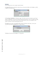
Defines the Panel ID within the Element Console to address. This number can be determined by telnetting to
the IP address of the element CPU on Port 4010, and tapping several of the buttons. For Example:
Open a command prompt on the windows PC and type Telnet IPAddress 4010 - “Telnet 172.168.2.3 4010”
Press Enter. This should open a Telnet session with the CPU.
Now tap several of the user panel buttons. You should see messages that look like:
EVENT MOD_USER#3.BUT#6 KEY=DOWN
EVENT MOD_USER#3.BUT#6 KEY=UP
The Module number is the one after the first # sign. In this case 3. This would be the number to enter in the
UserPanel Module field.
UserPanel Button
Identifies the number of the button on the panel to map to the software control. The bottom button is 1, and
they count up to the top of the panel. On a ten-button panel, the top button is ten. Once the UserPanel Mod-
ule and UserPanel Button properties are both entered, the HWMapAxiaSysName will automatically be filled in
accordingly.
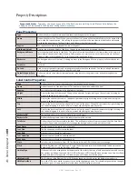
Meter Control Properties
Type
This defines the object type as Meter and cannot be changed by the designer.
Name
Defines the name of the Meter control. This name must be unique within the panel.
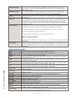
Caption
Sets the textual information to be displayed in the Meter. This is not currently used.
Height
The height of the control. Change this parameter by right-clicking on the control and resizing it or manually
editing this property value.
Width
Displays the width of the control. Change this parameter by right-clicking on the control and resizing it or
manually editing this property value.
Top
Displays the position of the top edge of the control on the panel. Change this parameter by right-clicking on
the control dragging it to a new location, or manually editing this property value.
Left
Displays the position of the left edge of the control on the panel. Change this parameter by right-clicking on
the control dragging it to a new location, or manually editing this property value.
Source/Dest
Defines whether the monitored I/O will be a source or a destination.
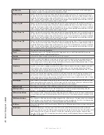
Router Number
Defines number of the router that will be used for this meter source or destination.
IO Number
Defines the number of the source or destination to monitor.
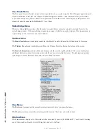
Scale
Used to select the numeric scale to be used for the meter – Standard, British, or Linear.
Style
Used to select the style as either led or gradient.
Line Color
Defines the color of level marking lines.
Decay Rate
Defines the decay rate for more natural metering. Approximately 3000ms generally yields good results.
Center Pad
Defines the space between the left and right meter. If expanded this also becomes the space designated for
level markings.


