32
ENGF-107 REV. A 01/11
© 2011 AXEON Water Technologies
FLUSHING THE SYSTEM
The system should be flushed weekly to remove sediment from the surface of the
membranes. To manually flush the system follow the preceding steps:
1. The system must be operating during the flush procedure.
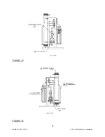
2. Fully open the concentrate valve. (Figure 1B, Page 16)
3. Allow the system to run for 10 to 20 minutes.
4. After 10 to 20 minutes, close the concentrate valve to its previous setting. Ensure
the proper concentrate flow rate is going to the drain.
5. The system is now ready to operate.
PREPARING UNIT FOR STORAGE OR SHIPMENT
Prior to shipping or storing your system, the system should be cleaned with an
appropriate cleaner, flushed with water, and protected from biological attack with an
appropriate solution for membrane elements. The membrane housing(s) and plumbing
lines of the system must be completely drained. Any water remaining in the plumbing of
a system may freeze, causing serious damage.
Preparing system for storage:
1. Totally immerse the elements in the membrane housing in a solution of 2 %
Memstor, venting the air outside of the pressure vessels. Use the overflow
technique: circulate the Memstor solution in such a way that the remaining air in
the system is minimized after the recirculation is completed. After the pressure
vessel is filled, the Memstor solution should be allowed to overflow through an
opening located higher than the upper end of the highest pressure vessel being
filled.
2. Separate the preservation solution from the air outside by closing all valves. Any
contact with oxygen will oxidize the Memstor.
3. Check the pH once a week. When the pH becomes 3 or lower, change the
preservation solution.
4. Repeat this process at least once a month.
During the shutdown period, the plant must be kept frost-free, or the temperature must
not exceed 113°F (45°C).
Preparing unit for shipment:
Содержание CT-4000
Страница 1: ...Reverse Osmosis User s Manual Model CT 4000 CT 5000 CT 7000 CT 7000 Pictured...
Страница 2: ...2 ENGF 107 REV A 01 11 2011 AXEON Water Technologies This Page Left Blank...
Страница 10: ...10 ENGF 107 REV A 01 11 2011 AXEON Water Technologies HF1 STANDARD...
Страница 11: ...11 ENGF 107 REV A 01 11 2011 AXEON Water Technologies HF4 OPTIONAL...
Страница 12: ...12 ENGF 107 REV A 01 11 2011 AXEON Water Technologies HF5 OPTIONAL...
Страница 13: ...13 ENGF 107 REV A 01 11 2011 AXEON Water Technologies NF3 OPTIONAL...
Страница 14: ...14 ENGF 107 REV A 01 11 2011 AXEON Water Technologies NF4 OPTIONAL...
Страница 15: ...15 ENGF 107 REV A 01 11 2011 AXEON Water Technologies CT 4000 CT 5000 CT 7000 SYSTEM IDENTIFICATION FIGURE 1A...
Страница 17: ...17 ENGF 107 REV A 01 11 2011 AXEON Water Technologies FIGURE 1B FIGURE 1C...
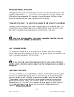
Страница 18: ...18 ENGF 107 REV A 01 11 2011 AXEON Water Technologies FIGURE 1D FIGURE 1E...
Страница 39: ...39 ENGF 107 REV A 01 11 2011 AXEON Water Technologies DRAWINGS FIGURE 5...
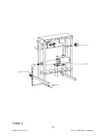
Страница 40: ...40 ENGF 107 REV A 01 11 2011 AXEON Water Technologies FIGURE 6...
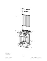
Страница 41: ...41 ENGF 107 REV A 01 11 2011 AXEON Water Technologies FIGURE 7...
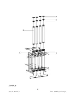
Страница 42: ...42 ENGF 107 REV A 01 11 2011 AXEON Water Technologies FIGURE 8...
Страница 47: ...47 ENGF 107 REV A 01 11 2011 AXEON Water Technologies CT 4000 FLOW DIAGRAM...
Страница 48: ...48 ENGF 107 REV A 01 11 2011 AXEON Water Technologies CT 5000 FLOW DIAGRAM...
Страница 49: ...49 ENGF 107 REV A 01 11 2011 AXEON Water Technologies CT 7000 FLOW DIAGRAM...
Страница 50: ...50 ENGF 107 REV A 01 11 2011 AXEON Water Technologies 110 220V 50 60 Hz 1 PHASE ELECTRICAL SCHEMATIC Minitrol...
Страница 51: ...51 ENGF 107 REV A 01 11 2011 AXEON Water Technologies 208 220V 50 60 Hz 3 PHASE ELECTRICAL SCHEMATIC Minitrol...
Страница 54: ...54 ENGF 107 REV A 01 11 2011 AXEON Water Technologies...

