29
ENGF-107 REV. A 01/11
© 2011 AXEON Water Technologies
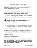
MEMBRANE REMOVAL & REPLACEMENT
Replacing membranes in the pressure vessels is an easy process if you have the
proper information and tools at hand. Please refer to the following instructions when
removing and replacing membrane elements:
WARNING: ALL PRESSURE GAUGES MUST READ ZERO BEFORE
PROCEEDING. BEFORE ATTEMPTING, DISCONNECT THE POWER FROM THE
SYSTEM AND BLEED ALL WATER PRESSURE FROM THE SYSTEM.
1. Remove the end caps from the top of the membrane housings. This is done by
removing the white snap ring of the membrane housing.
2. Remove the membrane bag containing the membrane element from the shipping
box.
WEAR GLOVES FOR THE FOLLOWING STEPS IN ORDER NOT TO
CONTAMINATE THE MEMBRANE.
3. Cut the bag open as close as possible to the seal at the end of the bag, so the
bag may be re-used if necessary.
4. Make sure that all parts are clean and free from dirt. Examine the brine seal, and
permeate tube for nicks or cuts. Replace the O-rings or brine seal if damaged.
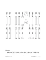
5. Flow directions should be observed for installation of each element into each
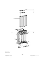
housing. (Figure 4, Page 30)
As time progresses, the efficiency of the membrane will be reduced. In general, the salt
rejection does not change significantly until two or three years after installation when
operated on properly pretreated feed water. The permeate flow rate will begin to decline
slightly after one year of operation, but can be extended with diligent flushing and
cleaning of the system. A high pH and/or precipitation of hardness can cause
premature loss in rejection.
REPLACING THE MEMBRANE ELEMENT:
WARNING: THE BRINE SEAL MUST BE IN THE SAME POSITION FOR
EACH MEMBRANE ELEMENT HOUSING, SO MARK EACH HOUSING PRIOR TO
REMOVING THE MEMBRANE ELEMENTS. THE BRINE SEAL IS A RUBBER SEAL
THAT PROTRUDES ON ONE SIDE OF THE MEMBRANE AND IS ALWAYS ON THE
FEED SIDE OF THE MEMBRANE ELEMENT.
Содержание CT-4000
Страница 1: ...Reverse Osmosis User s Manual Model CT 4000 CT 5000 CT 7000 CT 7000 Pictured...
Страница 2: ...2 ENGF 107 REV A 01 11 2011 AXEON Water Technologies This Page Left Blank...
Страница 10: ...10 ENGF 107 REV A 01 11 2011 AXEON Water Technologies HF1 STANDARD...
Страница 11: ...11 ENGF 107 REV A 01 11 2011 AXEON Water Technologies HF4 OPTIONAL...
Страница 12: ...12 ENGF 107 REV A 01 11 2011 AXEON Water Technologies HF5 OPTIONAL...
Страница 13: ...13 ENGF 107 REV A 01 11 2011 AXEON Water Technologies NF3 OPTIONAL...
Страница 14: ...14 ENGF 107 REV A 01 11 2011 AXEON Water Technologies NF4 OPTIONAL...
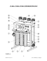
Страница 15: ...15 ENGF 107 REV A 01 11 2011 AXEON Water Technologies CT 4000 CT 5000 CT 7000 SYSTEM IDENTIFICATION FIGURE 1A...
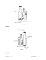
Страница 17: ...17 ENGF 107 REV A 01 11 2011 AXEON Water Technologies FIGURE 1B FIGURE 1C...
Страница 18: ...18 ENGF 107 REV A 01 11 2011 AXEON Water Technologies FIGURE 1D FIGURE 1E...
Страница 39: ...39 ENGF 107 REV A 01 11 2011 AXEON Water Technologies DRAWINGS FIGURE 5...
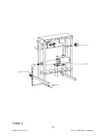
Страница 40: ...40 ENGF 107 REV A 01 11 2011 AXEON Water Technologies FIGURE 6...
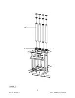
Страница 41: ...41 ENGF 107 REV A 01 11 2011 AXEON Water Technologies FIGURE 7...
Страница 42: ...42 ENGF 107 REV A 01 11 2011 AXEON Water Technologies FIGURE 8...
Страница 47: ...47 ENGF 107 REV A 01 11 2011 AXEON Water Technologies CT 4000 FLOW DIAGRAM...
Страница 48: ...48 ENGF 107 REV A 01 11 2011 AXEON Water Technologies CT 5000 FLOW DIAGRAM...
Страница 49: ...49 ENGF 107 REV A 01 11 2011 AXEON Water Technologies CT 7000 FLOW DIAGRAM...
Страница 50: ...50 ENGF 107 REV A 01 11 2011 AXEON Water Technologies 110 220V 50 60 Hz 1 PHASE ELECTRICAL SCHEMATIC Minitrol...
Страница 51: ...51 ENGF 107 REV A 01 11 2011 AXEON Water Technologies 208 220V 50 60 Hz 3 PHASE ELECTRICAL SCHEMATIC Minitrol...
Страница 54: ...54 ENGF 107 REV A 01 11 2011 AXEON Water Technologies...

